Description
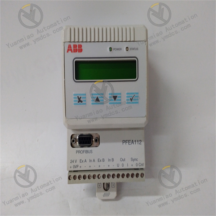
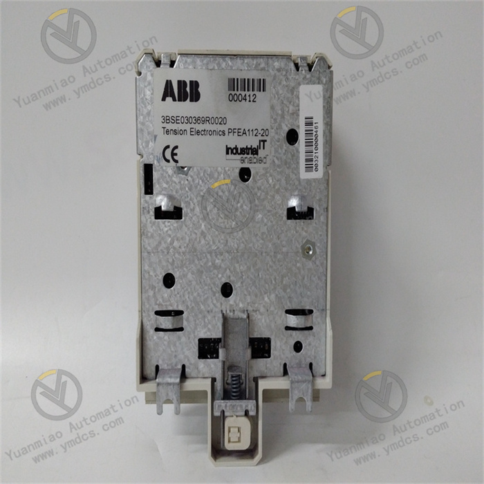
The ABB PFEA112-20 3BSE030369R0020 is a tension controller, mainly used for monitoring and adjusting the tension of materials during the production and processing process.
Working Principle: It can detect the tension of materials in real time through built-in sensors or by connecting to external sensors. The detected tension signal is converted into an electrical signal and compared with the preset tension value. According to the comparison result, the controller outputs corresponding control signals, and adjusts the tension of the materials through driving mechanisms such as motor drivers and brakes to keep it within the set range. Technical Parameters Operating Voltage: 230V. Output Frequency: 10kHz. Operating Temperature Range: -20°C to +70°C.
Application Scenarios Printing and Coating: In printing machines and coating equipment, it ensures that the printing materials or coatings maintain a stable tension throughout the printing or coating process, thus guaranteeing the printing quality and the uniformity of the coating. Paper and Coil Processing: In the production and processing of paper rolls, metal coils, plastic films, etc., it prevents the coils from being too tight or loose, improving production efficiency and product quality. Cable and Wire Production: On the production line of cables and wires, it ensures that the conductors and insulating materials are in the correct tension state throughout the manufacturing process, avoiding product defects caused by uneven tension. Textile Production: In the textile industry, it helps to ensure that the yarn maintains an appropriate tension throughout the textile process, reducing yarn breakage and twisting, and improving the quality of textiles. Common Faults and Solutions Unstable tension control: It may be due to sensor failure, unreasonable parameter settings, or problems with the driving mechanism. Solutions include checking the connection and performance of the sensor, readjusting the control parameters, and checking whether the driving mechanism is working properly. Unable to communicate normally: It may be due to poor communication line connection, incorrect communication protocol settings, or a fault in the communication module of the controller. It is necessary to check the communication line, verify the communication protocol settings, and if a communication module fault is suspected, try replacing the module. Abnormal display of the controller: It may be due to a display failure or a software problem inside the controller. Try restarting the controller. If the problem persists, contact the manufacturer for software upgrade or repair.
Steps for installation and debugging of ABB PFEA112-20 3BSE030369R0020: Installation Steps Preparation work: Ensure that the installation site environment meets the requirements, such as suitable temperature and humidity, and no strong electromagnetic interference. At the same time, prepare the required tools, such as screwdrivers and wrenches. Equipment inspection: Before installation, carefully check whether the PFEA112-20 module has any appearance damage, missing parts, etc., and confirm whether the model matches the system to be installed. Module installation: According to the installation manual of the equipment, install the PFEA112-20 module in the corresponding control cabinet or frame. Usually, screws or other fixing devices are required to firmly fix the module in the installation position to ensure a secure installation and prevent the module from loosening due to vibration or other reasons. Cable connection: Connect the power cable, communication cable, and connection cables to other relevant devices of the module correctly according to the wiring diagram. Pay attention to the firm connection of the cables to avoid poor contact, and also pay attention to grounding the shielding layer of the cables to reduce electromagnetic interference.

Debugging Steps
Power check: Before powering on, check again whether the power connection is correct and whether the power voltage meets the working requirements of the module. Generally, the working voltage of the ABB PFEA112-20 module has a specific range, and ensure that the input voltage is within this range.
Hardware initialization: After powering on the module, observe the status of the indicator lights. Some indicator lights will show the power status, communication status, etc. of the module. Usually, the power indicator light will turn on under normal circumstances, indicating that the module has received power. If the indicator lights show abnormalities, troubleshoot according to the instructions in the module manual.
Communication settings: Configure the communication parameters of the module, such as the communication protocol, baud rate, address, etc., according to the actual application scenario. These parameters need to match those of other connected devices (such as the host computer, controller, etc.) to ensure normal communication. For example, if using the Modbus protocol, set the correct baud rate, data bits, stop bits, and parity bits and other parameters.
Function test: Send test commands to the PFEA112-20 module through the host computer software or other test tools to check whether all functions of the module are normal. For example, test the analog input and output functions, digital input and output functions, etc. For analog input, input different analog signals to check whether the module can correctly collect and convert data; for analog output, set different output values to check whether the module can accurately output the corresponding analog signals. For digital input and output, change the state of the input signal to check whether the output signal changes as expected.
System joint debugging: Conduct joint debugging of the PFEA112-20 module with other devices in the entire system. In the actual operation environment, check whether the data interaction between the module and other devices is normal, and whether the overall function of the system meets the design requirements. For example, in an automated control system, check whether the data collected by the PFEA112-20 module can be correctly transmitted to the controller, and whether the commands issued by the controller can accurately control the relevant devices through the module.