Description
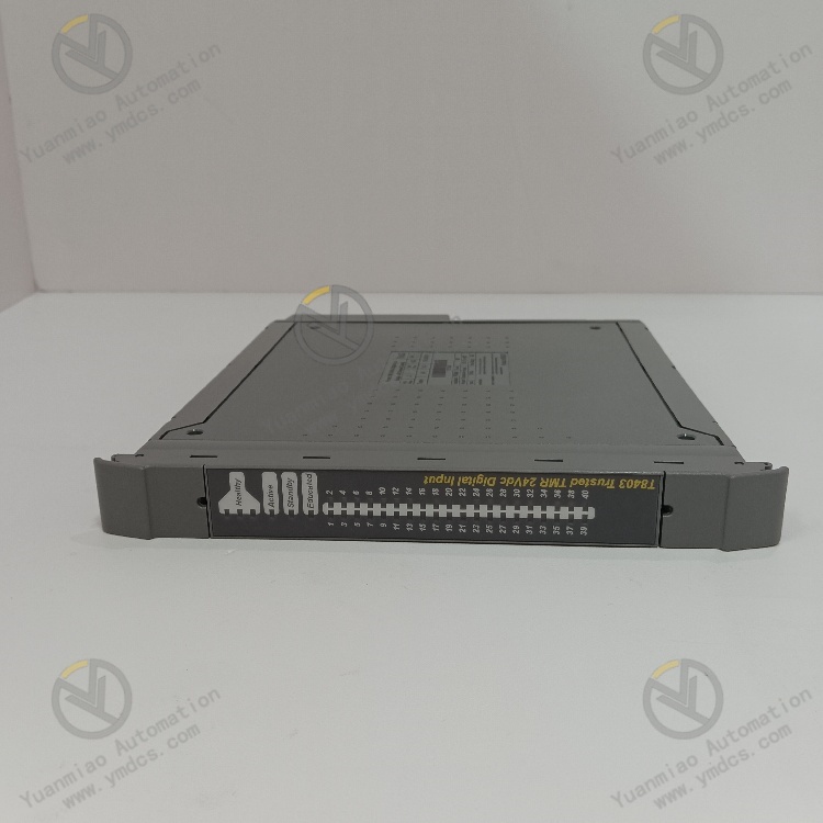
ICS Triplex T8403C
Functional Features
- Multi-Channel and Redundant Design: Each module has 40 Triplex Modular Redundancy (TMR) input channels, providing high reliability and fault tolerance for each channel.
- Automatic Diagnosis and Self-Test: Equipped with comprehensive automatic diagnosis and self-test functions to promptly detect faults within the module.
- Line Monitoring: Line monitoring can be selected for each channel to independently detect field wiring faults such as open circuits and short circuits, improving system stability.
- Isolation Protection: A 2500V impulse-resistant optoelectric/current isolation barrier effectively isolates external interference and protects the module and system from electrical surges.
- Sequence of Events (SOE) Reporting: Features onboard SOE reporting with 1ms resolution, where state changes trigger SOE records for precise traceability and analysis of system events.
- Digital Filtering: Configurable 50/60Hz digital filtering eliminates field-induced noise to ensure input signal accuracy.
- Hot Replacement Function: Online hot replacement of modules is supported via dedicated companion (adjacent) slots or SmartSlots (a shared backup slot for multiple modules), facilitating maintenance and reducing system downtime.
Technical Parameters
- Operating Voltage: 24Vdc
- Number of Channels: 40 digital input channels
- Isolation Characteristics: 2500V impulse-resistant optoelectric/current isolation barrier
- Filter Configuration: Configurable 50/60Hz digital filtering
- SOE Resolution: 1 millisecond
- Certification: Compliant with IEC 61508 SIL 3 certification, suitable for industrial automation systems with high safety requirements.
- Dimensions: Approximately 9.3cm×30.2cm×26.5cm
- Weight: 3.06kg

Working Principle
- Measures input voltage through a sigma-delta input circuit and compares the measured field voltage with user-configurable threshold voltages to determine the reported field input state.
- Utilizes the TMR architecture within the module to triplicate each field input for fault tolerance. Triple voltage measurements combined with onboard diagnostic tests provide comprehensive fault detection and tolerance.
Operation Guide
- Installation: Select an appropriate installation location to ensure the module is securely mounted. Follow the manual to connect power, communication interfaces, and other related devices, ensuring correct and stable wiring.
- Configuration: Use corresponding configuration software to connect to the module via communication interfaces and set parameters such as communication parameters, digital filtering parameters, line monitoring configuration, and threshold voltages to meet specific application requirements.
- Daily Operation: Operators can obtain collected data and status information through the module’s communication interfaces via relevant monitoring systems or devices, and view equipment operating status and SOE reports. Adjust parameters of the module through configuration software or the host computer system as needed.
- Maintenance and Troubleshooting: Regularly inspect the module’s operating status, including communication integrity and data acquisition accuracy. In case of faults, refer to the manual for troubleshooting and repair based on the module’s alarm information, indicator light status, and system logs. Contact professional technicians for complex faults. Since the module supports hot-swapping, it can be replaced while the system is running to minimize downtime.

Common Faults and Solutions
- Communication Faults: May be due to poor communication line connections, incorrect communication parameter settings, or faulty module communication interfaces. Check line connections to ensure they are secure and undamaged; verify that communication parameters match those of other devices; if module faults are suspected, replace the module and contact professionals for repair.
- Abnormal Input Signals: Causes may include sensor faults, incorrect input channel configuration, or damaged channel hardware. Inspect sensor operation and measure their output signals; verify that input channel configuration parameters match the actual sensors; determine if channel hardware issues exist through comparative testing and contact maintenance or replace the module if necessary.
- Module Overheating: May be due to poor ventilation at the installation location or high ambient temperatures. Improve the module’s installation environment to ensure adequate surrounding space for heat dissipation, clean dust from cooling channels, and take cooling measures such as installing fans or air conditioners if necessary.