Description
Functional Characteristics
High Reliability: Alstom's modules typically adopt redundant design, fault-tolerant mechanisms, and high-quality electronic components to ensure long-term stable operation in critical fields such as rail transit. They maintain high reliability even under harsh environmental conditions, reducing the probability of failures and ensuring continuous system operation.
Strong Processing Capability: Equipped with high-performance microprocessors or digital signal processors (DSPs), they feature fast data processing and computing capabilities. They can real-time process signals from various sensors and controllers in rail transit systems to achieve precise monitoring and control of train operation status.
Diverse Interface Types: To enable effective communication and data interaction with other devices, they may provide multiple standard interfaces such as Ethernet, serial ports, and CAN bus interfaces. This facilitates connection with train control systems, signaling systems, and monitoring systems to achieve information sharing and collaborative operation.
High-Precision Signal Acquisition and Processing: When monitoring train operation parameters (e.g., speed, position, current, voltage), the module may have high-precision analog input channels. These channels can accurately collect weak signals from various sensors and perform precise analog-to-digital conversion and digital signal processing, providing accurate data support for train control and protection.
Application Scenarios
Train Control and Monitoring: Used in train control systems to collect and process signals from various sensors (e.g., speed sensors, position sensors, pressure sensors) to real-time monitor train operation status, including speed, position, door status, and braking status. This information is transmitted to the train's central control system for precise control and decision-making.
Signaling System Interface: As part of the rail transit signaling system, it communicates with ground signaling equipment and on-board signaling devices to enable information interaction between trains and the signaling system. This ensures trains can operate safely and accurately according to signaling instructions, such as receiving track circuit signals and sending train position information to ground signaling systems.
Vehicle Electrical System Control: Manages and controls train electrical systems, such as traction systems, auxiliary power systems, and lighting systems. It enables start/stop control, parameter adjustment, and fault diagnosis for vehicle electrical equipment to ensure normal operation of the train's electrical system.
Fault Diagnosis and Early Warning: Leveraging its strong processing capabilities and built-in diagnostic algorithms, it analyzes and processes collected data to promptly detect abnormal conditions and potential faults during train operation and issue corresponding alarms. This allows maintenance personnel to take timely action, improving train safety and maintainability.
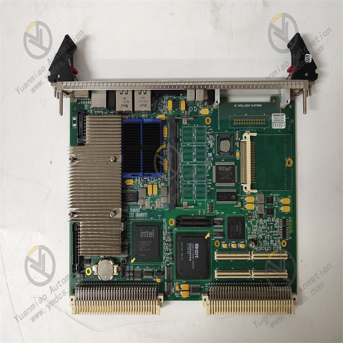
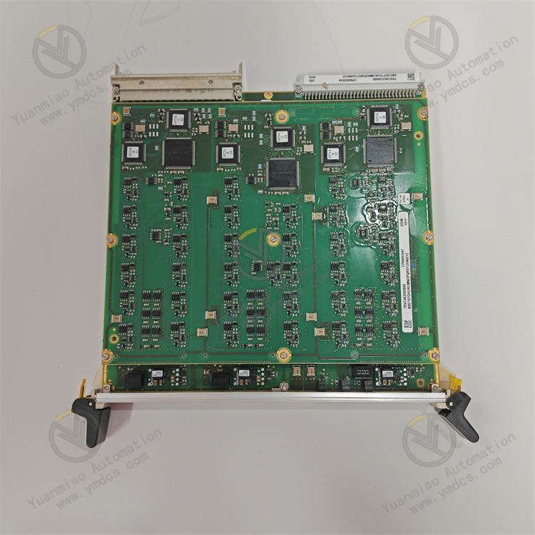
The ALSTOM VIIB16-C 12011-105-00 module is a digital input module in the rail transit field (typically used to collect external train signals such as switch signals and sensor status). Below are common fault types, possible causes, and troubleshooting directions in rail transit for reference:
I. Power and Physical Connection Faults
1. No Power Supply to Module (Power Indicator Off)
- Possible Causes:
- External power supply failure (e.g., unstable voltage, reverse polarity, blown fuse).
- Loose or poor contact at power terminals, or incorrect wiring (e.g., improper connection of DC 24V positive/negative poles).
- Internal power circuit damage (e.g., swollen capacitors, burnt chips).
- Impact: The module cannot operate, and all input channels fail.
- Troubleshooting Suggestions:
- Measure the voltage at the power terminals with a multimeter to confirm it matches the module's rated value (e.g., DC 24V ±10%).
- Inspect power cables for damage, tighten terminal block screws, and try replacing the power supply or cable.
2. Module Overheating or Abnormal Heating
- Possible Causes:
- Poor ventilation in the installation environment, with cooling holes blocked by dust.
- The module operates long-term in an environment exceeding the rated temperature (e.g., >60°C).
- Aging or short-circuit of internal components (e.g., leaking electrolytic capacitors, integrated circuit failures).
- Impact: May trigger overheat protection, leading to intermittent failure or permanent damage.
- Troubleshooting Suggestions:
- Clean dust from the module surface and installation rack to ensure good ventilation.
- Use an infrared thermometer to detect the module's surface temperature. If exceeding the rated value, improve heat dissipation or replace the module.
II. Communication and Data Transmission Faults
1. Communication Interruption (Abnormal Communication Indicator)
- Possible Causes:
- Loose, broken, or poorly shielded/grounded communication bus cables (e.g., CANopen, MVB, Profibus).
- Communication address conflicts (e.g., duplicate slave addresses) or parameter configuration errors (mismatched baud rate, parity bit).
- Faulty communication chips or abnormal firmware (e.g., program crashes, incompatible firmware versions).
- Impact: The module cannot exchange data with train control systems (e.g., PLC, TCMS), causing signal acquisition to fail.
- Troubleshooting Suggestions:
- Use an oscilloscope or multimeter to detect bus signal waveforms and confirm signal attenuation or interference.
- Reset communication parameters via configuration software (e.g., ALSTOM Unity Pro) and check slave address uniqueness.
- Try restarting the module or upgrading the firmware to the latest version.
2. Data Transmission Errors or Loss
- Possible Causes:
- Electromagnetic interference (e.g., high-frequency noise from traction motors, inverters) affecting bus signals.
- Excessive communication cable length or lack of shielded cables, causing signal attenuation.
- Internal communication buffer errors or hardware failures (e.g., memory damage).
- Impact: Misreporting of input signal status (e.g., misreading as "1" or "0"), potentially causing abnormal train control logic.
- Troubleshooting Suggestions:
- Add shielding layers to communication cables, ground them reliably, and keep them away from strong electromagnetic sources.
- Shorten bus length or add repeaters to ensure signal strength meets standards.
- Read module error logs via diagnostic software to check for CRC errors, timeouts, etc.
III. Input Channel Function Abnormalities
1. Single or Multiple Input Channels Unresponsive
- Possible Causes:
- External signal source failure (e.g., oxidized switch contacts, damaged sensors).
- Loose, short-circuited, or overloaded input terminals (e.g., voltage exceeding the rated value).
- Internal channel circuit damage (e.g., burnt current-limiting resistors, failed optocouplers).
- Impact: Corresponding channels cannot collect signals, potentially disabling related control functions (e.g., door status detection, brake signal acquisition).
- Troubleshooting Suggestions:
- Measure input terminal voltage with a multimeter to confirm normal external signals (e.g., DC 24V input reaching the threshold).
- Short the input terminals and observe if the module's indicator lights up. If not, test with a spare channel.
- If multiple channels fail simultaneously, check for poor backplane bus contact or internal motherboard issues, and replace the module if necessary.
2. False Input Signal Triggering (Abnormal Indicator Lighting)
- Possible Causes:
- Inductive voltage or crosstalk in external lines (e.g., parallel routing with power cables).
- Improper module input filter parameter settings (e.g., too short filtering time to suppress interference pulses).
- Reduced channel insulation performance causing leakage current false triggering.
- Impact: The train control system receives erroneous signals, potentially triggering misoperations (e.g., false emergency braking).
- Troubleshooting Suggestions:
- Check if input cables are routed separately from high-voltage cables and add isolation measures (e.g., relay isolation).
- Adjust input filtering time via configuration software (e.g., extend to over 10ms) to suppress high-frequency interference.
- Measure input channel leakage current. If exceeding the rated value (e.g., >1mA), replace the module.
IV. Mechanical and Environmental Faults
1. Module Loose or Poor Contact
- Possible Causes:
- Loose mounting screws, causing the module to detach from the backplane or rail in a vibrating environment (e.g., during train operation).
- Oxidized, bent, or broken connector pins, leading to electrical connection failures.
- Impact: Intermittent communication interruptions or unstable input signals, difficult to locate.
- Troubleshooting Suggestions:
- After shutdown, check module mounting stability, reinsert the module, and tighten screws.
- Visually inspect connector pins, clean oxidation, or replace damaged connectors.
2. Faults Caused by Environmental Stress
- Possible Causes:
- Long-term vibration causing internal component solder joint failure (e.g., BGA chip cold soldering).
- Circuit board corrosion or reduced insulation due to a humid environment.
- Contaminants such as salt spray or dust entering the module, causing short circuits or poor contact.
- Impact: Reduced module reliability, potentially leading to intermittent faults or permanent damage.
- Troubleshooting Suggestions:
- Perform vibration tests on the module (simulating train operating conditions) to check for loose components.
- Regularly clean the module surface and apply moisture/dust protection (e.g., 三防漆 three-proof coating) if necessary.

V. General Fault Troubleshooting Process
Initial Observation:
- Check indicator status (e.g., power light, run light, channel status lights) and record the color and flashing frequency of abnormal lights.
Segmented Testing:
- Troubleshoot layer by layer from the external signal source → module input terminals → communication bus → control system to isolate fault points.
Replacement Verification:
- Replace the faulty module with an identical normal one. If the system recovers, the original module has a hardware fault.
Log Analysis:
- Read error codes via the train diagnostic system or module configuration software and refer to the ALSTOM official manual to locate issues (e.g., code "E01" indicates channel overload).
Precautions
Safety Operations: When operating modules in rail transit systems, power off first and confirm the train is in a safe shutdown state to avoid affecting traffic safety.
Spare Parts Management: It is recommended to equip spare parts for modules in critical positions to quickly replace faulty modules and reduce downtime.
Preventive Maintenance: Regularly clean, tighten, and functionally test modules, especially increasing maintenance frequency in high-vibration and high-humidity environments.