Description
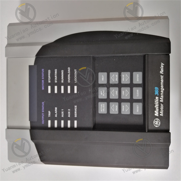
GE Multilin 369-HI-R-M-0-0-0-0
Overview
The GE Multilin 369-HI-R-M-0-0-0-0 is a powerful and highly reliable motor management relay belonging to the GE Multilin series, renowned for its exceptional performance and advanced technology in industrial applications. Specifically designed for protection and monitoring of medium to large three-phase motors and their associated systems, this relay effectively addresses complex industrial environments, ensuring stable and efficient motor operation. It is widely used in industries such as power, petrochemical, industrial automation, and building automation.
Functional Features
Comprehensive Protection Functions
- Electrical Fault Protection:
- Overload Protection: Continuously monitors motor current and triggers a trip if the current exceeds the preset overload threshold for a specified duration, preventing overheating and damage.
- Under-Voltage Protection: Detects voltage drops below the specified level, either tripping the motor to avoid stalling due to insufficient power or enabling under-voltage auto-restart once voltage recovers.
- Over-Voltage Protection: Protects the motor from insulation breakdown by disconnecting it from the power source when voltage exceeds the upper limit.
- Short-Circuit Protection: Responds within milliseconds to short-circuit faults, preventing severe damage to the motor and other electrical components.
- Ground Fault Protection: Identifies ground faults to ensure system and personnel safety.
- Current Imbalance Protection: Monitors three-phase current imbalance to detect potential issues like broken rotor bars or winding faults.
- Mechanical Fault Monitoring:
- Mechanical Jam Detection: Senses jams (e.g., blocked fans or seized bearings) by monitoring motor acceleration time and current characteristics, triggering protective actions.
- Stator & Bearing RTD Monitoring: Features 12 optional RTD inputs to real-time monitor stator winding and bearing temperatures, triggering alarms or trips for abnormal temperature rises.
Real-time Monitoring Capabilities
- Real-time Parameter Measurement: Continuously measures electrical parameters (voltage, current, power [kW, kVA, kvar], power factor, frequency) with high precision, providing critical data for system analysis, energy management, and predictive maintenance.
- Event Logging: Stores extensive event records (trips, alarms, operational changes) for post-fault root cause analysis, optimizing system operation and maintenance strategies.
Flexible Configuration Options
- Adaptive Parameter Learning: The relay’s intelligent "learning" function adapts to specific motor parameters (inrush current, cooling rate, acceleration time) based on actual operation, enabling precise personalized protection and control.
- Customizable Settings: Users can adjust protection thresholds, trip times, alarm levels, etc., via the front-panel keypad or Enervista 369 setup software (with PC), meeting diverse needs for different motors and applications.
Technical Parameters
| Category | Specifications |
|---|---|
| Control Power | DC: 50–300 VDC AC: 60–265 VAC, 50/60 Hz Nominal: 20 VA; Maximum: 65 VA |
| Current Inputs | For 50/60 Hz nominal frequency: 0.05–20 × CT primary amps (measurement range), true rms measurement, 1.04 ms/sample sampling rate |
| RTD Inputs | 12 optional RTD inputs, user-definable RTD type |
| Outputs | 4 alarm outputs, 2 trip outputs (non-failsafe trip: 200 ms; failsafe trip: 100 ms) |
| Communication | 1 front-panel RS232 port, 3 rear-panel RS485 ports, standard Modbus RTU protocol; Optional interfaces: Modbus/TCP, Profibus-DP, Profibus-DPv1, DeviceNet (with additional configurations); user-definable baud rate (1200–19200) |
| Dimensions | Approx. 144 mm (H) × 168 mm (W) × 222 mm (L) |
| Weight | Approx. 4.5 kg |
| Environmental | Operating temp: –25°C to +70°C; Storage temp: –40°C to +85°C; Humidity: 5%–95% RH (non-condensing) |
Working Principle
Protection Logic Operation
The relay continuously monitors input signals from current transformers (CTs), voltage transformers (VTs), and RTDs. For electrical protection, it compares real-time current, voltage, and power measurements against pre-set thresholds. For example, if measured current exceeds the overcurrent setpoint for longer than the trip time, the protection logic triggers the trip output to isolate the motor via the circuit breaker. For mechanical protection, it analyzes operational parameters (e.g., actual vs. expected acceleration time) to detect jams and activate protective responses.
Data Acquisition & Processing
Analog signals from CTs and VTs are converted to digital values by high-precision ADCs, then processed by a microprocessor to calculate parameters (power, power factor, frequency). Temperature data from RTDs is also acquired: the relay converts RTD resistance changes (due to temperature) into digital values, comparing them against set thresholds for protection and monitoring.
Communication & Interface Functions
Via RS232/RS485 ports, the relay exchanges data with SCADA systems and other devices using standard Modbus RTU protocol, sending real-time parameters/event logs and receiving configuration commands. Optional communication interfaces expand connectivity, enabling seamless integration into diverse industrial networks for efficient remote monitoring and control.
Operation Guide
Installation Steps
- Mounting Location & Fixing: Install the relay in a standard 19-inch rack or suitable electrical enclosure, away from strong EMI sources. Use provided brackets and screws for secure fixing.
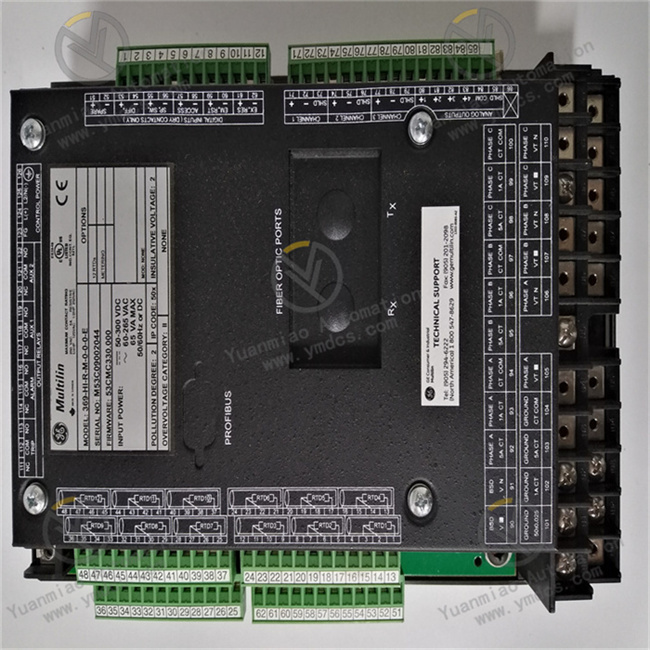
- Wiring:
- Power Connection: Connect control power (DC/AC) to designated terminals, ensuring correct polarity (DC) or phase sequence (AC).
- CT/VT Input Wiring: Connect CT/VT secondary wires to input terminals, grounding CTs/VTs properly to prevent electrical hazards.
- RTD Connection: If using RTDs, connect wires to 12 RTD input terminals with correct wire types and configurations for accurate temperature measurement.
- Output Connection: Connect alarm/trip output wires to control devices (e.g., alarm indicators, circuit breakers).
Configuration Methods
- Local Configuration: Access the menu via front-panel keys to set basic parameters (CT/VT ratios, protection enable/disable, alarm thresholds).
- Remote Configuration: Use Enervista 369 setup software (via RS232/RS485) for advanced settings (protection curves, communication protocols, event logging).
Troubleshooting
- Power Issues: Check power connections, fuse status, and verify voltage within the specified range if the relay fails to power on.
- False Tripping: Review protection settings for consistency with motor operation; check CT/VT wiring for looseness/damage that may cause inaccurate measurements.
- Communication Failures: Verify cable connections and matching communication parameters (baud rate, protocol) on both the relay and external devices. For optional interfaces, ensure correct hardware/software configurations.