Description
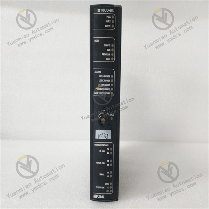
I. Check Module Physical Status and Indicator Lights
| Indicator Type | Normal Status | Abnormal Status and Possible Causes |
|---|---|---|
| Power Indicator (PWR) | Steady on (green) | Off: Power not connected, module failure, or power supply damage |
| Run Indicator (RUN) | Periodic flashing (e.g., once per second, green) | Off or steady on: Module not started or abnormal program operation |
| Communication Indicator (COM) | Flashing during data transmission (green/orange) | Off: Communication link interruption or parameter configuration error |
| Fault Indicator (FAULT) | Off | Steady on (red): Internal module fault, overheating, or configuration error |
| I/O Status Indicator | Dynamically changes with input/output signals (e.g., lights up when input is active) | Fixed status: Damaged I/O channel or abnormal external signal |
Operation Recommendations:
- Verify that the power supply voltage meets the module requirements (e.g., DC 24V or AC 110/220V) and check that the power cable connections are secure.
- If the FAULT light is on, first inspect the module's heat dissipation (e.g., dust accumulation, excessively high ambient temperature) or try restarting the module.
II. Test Communication Functions
The I/OBUS2 module is typically used for industrial bus communication (e.g., Profibus, Modbus, CAN, etc.). It is necessary to verify its normal communication with the controller or host computer:
1. Check Communication Parameter Configuration
- Confirm module address: Ensure the module has a unique address on the bus (e.g., the Profibus slave address must match the configuration).
- Verify communication protocol and baud rate: Use module configuration software (such as ALSTOM's proprietary tools or general debugging software) to check parameters like protocol type (e.g., Profibus DP, Modbus RTU), baud rate, and parity bit for matching with the master station.
- Example tools: For modules supporting Profibus, use ProfiTrace or SIMATIC Step 7 to scan the slave status; for Modbus, use Modbus Poll/Slave tools to test data transmission and reception.
2. Communication Connectivity Test
- Ping test (Ethernet module): If the module supports Ethernet, ping the module via its IP address to check for packet loss or excessive latency.
- Data read/write test:
- Send data from the host computer (e.g., PLC, SCADA system) to the module and observe whether the module correctly receives and feeds back the data.
- Simulate external signals (e.g., digital input signals) and check whether the host computer can read the module's I/O status in real time.
3. Fault Troubleshooting Directions
- Communication interruption: Check for damaged network or bus cables and loose connectors; replace with a module of the same type to rule out hardware failures.
- Abnormal data: If data transmission is garbled, it may be caused by protocol mismatch, incorrect baud rate, or electromagnetic interference. Try reducing the baud rate or adding shielding measures.
III. Verify I/O Functions
If the module includes I/O channels (e.g., digital input/output, analog channels), test their input response and output driving capabilities:
1. Input Channel Test
- Digital Input (DI):
- Short the input terminals, observe whether the module's input indicator light turns on, and check whether the corresponding channel status reads "1" via the host computer.
- Disconnect the short, and the status should revert to "0".
- Analog Input (AI):
- Apply a standard signal (e.g., 4-20mA, 0-10V), confirm the signal is correct with a multimeter, and then check whether the module's collected value matches the actual value (the error must be within the allowable range, e.g., ±1% FS).
2. Output Channel Test
- Digital Output (DO):
- Send a command from the host computer to force the output channel to "1", observe whether the output indicator light turns on, and use a multimeter to measure whether the voltage between terminals meets expectations (e.g., 24V or relay contact on/off).
- Note: If the output is loaded (e.g., solenoid valves, motors), ensure the module's capacity matches to avoid overload damage.
- Analog Output (AO):
- Send a set value (e.g., 12mA, 5V) and use a multimeter to measure whether the signal at the output terminal is stable and accurate.
3. Exception Handling
- If a channel does not respond, first check for loose external wiring, then test with a spare channel to determine whether the issue is a damaged channel or overall module failure.
- For relay output modules, if contacts are stuck (unable to disconnect), this may be caused by frequent start/stop operations or excessive load. Replace the module or upgrade the load protection circuit.
IV. Use Diagnostic Tools and Log Analysis
1. Dedicated Software Diagnosis
- ALSTOM modules may come with programming software such as Unity Pro to monitor module status in real time:
- Check the module's online status (e.g., displayed as "Running" or "Fault").
- Read error codes in the diagnostic buffer (e.g., timeout, checksum error, hardware fault codes) and refer to the manual to locate issues.
- Example: If the software prompts "Slave timeout," it may indicate a communication link interruption or incorrect module configuration.
2. Firmware Version Check
- Outdated firmware may cause compatibility issues or functional abnormalities. Check whether the module's firmware version is the latest via software and upgrade it as needed according to official guidelines.
V. Comparison and Replacement Testing
1. Comparison with Similar Modules
- If there are multiple identical modules in the system, compare the indicator status, parameter configurations, and data read/write behavior between the normal module and the faulty module to quickly locate differences (e.g., address conflicts, corrupted configuration files).
2. Replacement Verification
- Install the Suspected faulty module in a normally working station or replace the original module with a known-good one:
- If the system resumes normal operation after replacement, the original module has a hardware failure (e.g., damaged chip, swollen capacitor) and needs repair or replacement.
- If the fault persists, "Troubleshoot peripheral circuits (e.g., power supply, bus coupler) or system configuration issues.
VI. Precautions
- Safety operations: Disconnect the power supply before disassembling or wiring the module to avoid electrostatic damage to electronic components.
- Environmental factors: High temperature, humidity, or strong electromagnetic interference may cause module abnormalities. Ensure the installation environment meets the manual requirements (e.g., temperature -20°C~+60°C, humidity <95% non-condensing).