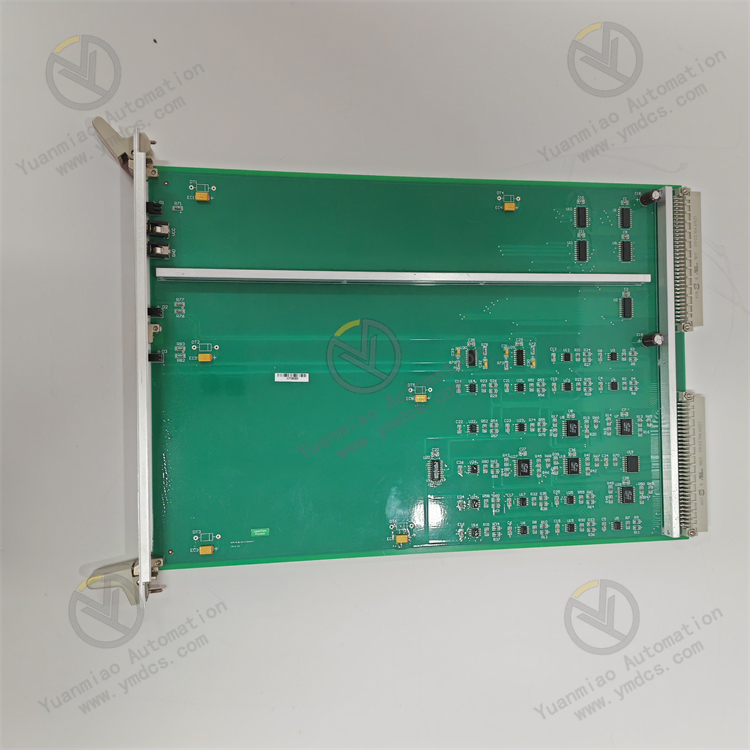
Description
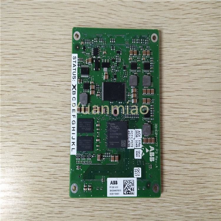
Functional Role: In the iLOCK system, the I/OBUS2 board exchanges information with the I/OBE2 board. The I/OBE2 board achieves differential driving to power the double-break output board, providing input/output signal expansion and driving functions for the system. This ensures accurate transmission and processing of signals between different boards, making it a critical component for implementing input/output functions in the interlocking system.
Application Scenarios: Primarily used in railway signal interlocking systems, such as the iLOCK system, to realize functions like railway station signal control, switch control, and signal light control, ensuring the safe operation and efficient scheduling of trains.
Installation and Maintenance:
- Installation: Must comply with relevant railway signal system installation specifications to ensure secure board mounting and correct wiring. Anti-static measures (e.g., grounding) are required to prevent board damage from electrostatic discharge.
- Maintenance: Regularly inspect the board's operating status using the system's diagnostic functions or monitoring equipment to check for fault alarms. Address issues promptly and keep the equipment clean to avoid performance degradation from dust or debris.
Technical Parameters
1. Electrical Parameters
- Power Supply Voltage:
- DC: Typically 24V DC (±10%), with some models supporting wide voltage input (e.g., 10–30V DC).
- AC: May be 100–240V AC (50/60Hz); refer to the manual for specifics.
- Power Consumption: Typical 5–20W, depending on the module type (e.g., digital I/O, analog I/O, or communication module).
- Isolation Characteristics:
- Inter-channel isolation voltage: Usually ≥500V AC (RMS) to prevent signal interference.
- Power and signal isolation: Supports optoelectronic or electromagnetic isolation to enhance anti-interference capabilities.
2. I/O Characteristics (Digital Module Example)
- Input Channels:
- Channel count: 8/16/32 points (estimated), supporting dry or wet contact inputs.
- Input type: DC input (e.g., 24V DC) or AC input (e.g., 120V AC).
- Response time: Typical 5–20ms (filter adjustable).
- Output Channels:
- Relay output: Supports AC/DC loads, with contact ratings such as 2A/250V AC.
- Transistor output (DC): NPN/PNP types, with maximum current 0.5–2A.
- Thyristor output (AC): Triac-based, suitable for AC loads.
- Channel count: 8/16/32 points (estimated), with possible output types including:
3. Communication and Interfaces
- Communication Protocols:
- Supports industrial bus protocols such as Modbus RTU/TCP, CANopen, Profinet, EtherCAT, etc.
- Alstom-proprietary protocols (e.g., TCN bus for rail transit).
- Interface Types:
- Physical interfaces: RJ45 (Ethernet), DB9 (serial), terminal blocks (I/O signals).
- Baud rates: Serial supports 9.6k–115.2k bps; Ethernet supports 10/100Mbps.
4. Mechanical and Environmental Parameters
- Installation Methods: Rail mounting (e.g., DIN rail) or panel mounting, supporting vertical or horizontal installation.
- Dimensions: Typical module width ~22.5–45mm (per I/O module), depth ~100–150mm.
- Operating Temperature: Industrial standard (-20°C ~ +60°C); some models support wide temperature ranges (-40°C ~ +85°C).
- Protection Level: IP20 (indoor protection), dust and splash-proof.
- Vibration/Shock: Complies with IEC 61373 (rail transit) or IEC 60068-2 standards.
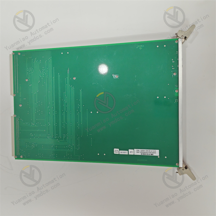
Common Faults and Solutions for ALSTOM I/OBE2 12004-104-00 Module
I. Common Fault Types and Possible Causes
- Power Supply Faults
- Symptoms: No power supply, unlit indicator lights, frequent restarts.
Possible Causes:
- Unstable external power voltage (e.g., DC supply deviating by ±10% from rated value).
- Loose power connections, oxidized terminals, or blown fuses.
- Internal power circuit damage (e.g., swollen capacitors, burnt chips).
- Communication Faults
- Symptoms: Failure to communicate with the main control system (e.g., PLC, DCS); abnormal communication indicator lights (constantly off or flashing rapidly).
Possible Causes:
- Mismatched communication protocols (e.g., incorrect baud rate, parity, data bit settings).
- Damaged, loose, or poorly grounded communication cables (especially in high-frequency interference environments).
- Faulty module communication interface chip or incompatible firmware version.
- I/O Signal Anomalies
- Symptoms: Unresponsive input signals, uncontrolled output signals (e.g., relays not operating, analog signal fluctuations).
Possible Causes:
- Input signals exceeding rated ranges (e.g., voltage/current overload).
- Output load short circuits or overloads triggering module protection functions.
- Loose I/O terminal blocks or internal circuit aging due to long-term operation.
- Overheating or Environmental Faults
- Symptoms: Excessive module temperature, stalled cooling fans, or fault alarms due to environmental humidity/dust.
Possible Causes:
- Poor ventilation in the installation environment, blocked cooling vents.
- Faulty fans or detached heat sinks causing overheating and component damage.
- Excessive environmental humidity leading to circuit board short circuits or corrosion.
- Hardware Faults (Non-Volatile Faults)
- Symptoms: Frequent hardware error messages (e.g., "EEPROM fault," "firmware checksum failure").
Possible Causes:
- Damaged internal memory (EEPROM/FLASH) or data loss (caused by power transients or electromagnetic interference).
- Faulty main chips or FPGA logic, typically due to overvoltage or electrostatic discharge (ESD).
II. General Solutions
- Power Supply Fault Troubleshooting
- Steps:
- Measure input voltage with a multimeter to confirm it is within the rated range (e.g., DC 24V ±10%).
- Inspect power terminal connections; re-plug or replace cables to ensure secure connections.
- Replace fuses with the same specification if the module has built-in fuses (power off before operation).
- If the power supply is normal but the module is unresponsive, internal power module damage is likely; contact Alstom after-sales service or return for repair.
- Communication Fault Troubleshooting
- Steps:
- Verify that communication parameters (e.g., Modbus RTU baud rate, slave address) match the main control system.
- Replace communication cables or switch interfaces (e.g., from RS-485 to RS-232) to test for cable issues.
- Use an oscilloscope or communication test tools (e.g., Modbus Poll) to monitor communication waveforms for interference or signal attenuation.
- Attempt to update the module firmware to the latest version (via Alstom official software).
- I/O Signal Fault Troubleshooting
Input Signals:
- Measure actual signal values at input terminals with a multimeter to confirm consistency with system readings.
- Check sensor or external device outputs to rule out front-end faults.
Output Signals:
- Disconnect loads to test module outputs (e.g., relay contact switching, analog output voltage/current).
- If issues arise under load, check whether the load impedance is within the module's rated range to avoid overload.
- Clean I/O terminal blocks and replace terminals or pins if necessary.
- Overheating and Environmental Management
- Steps:
- Clean dust from module cooling vents and fans to ensure air circulation.
- Check fan operation; replace fan components if stalled.
- Measure environmental temperature and humidity to ensure they meet module specifications (typically industrial-grade: -20°C~60°C, humidity <90% non-condensing).
- In harsh environments (e.g., high dust, corrosive gases), consider adding protective enclosures or scheduling regular maintenance.
- Hardware Fault Handling
Non-Volatile Faults:
- Restore factory settings (if supported) or reflash firmware via official software.
- If errors persist, hardware failure is likely; replace the module or seek professional repair.
Precautions:
- Backup module configuration data before operations to avoid loss due to firmware update failures.
- Wear anti-static wristbands when handling electrostatic-sensitive components to avoid direct contact with circuit boards.