Description
VMIC VMIVME-4140
I. Basic Information
Model: VMIVME-4140 (VMIVME-4140-000: 32CH / VMIVME-4140-001:16CH)
Brand: VMIC (GE Fanuc, now Abaco Systems)
Product Line: 6U VME bus high-precision analog output board, each channel equipped with independent 12-bit DAC chip. It converts digital control commands from VME host into standard industrial voltage signals for closed-loop regulation of control valves, inverters and actuators, widely applied in power generation, rail transit, aerospace ATE test and safety critical industrial control systems.
Product Positioning
VMIVME-4140 is a high-density VME AO module supporting 16/32 channel options. Adopting independent per-channel DAC and double-buffered synchronous output architecture, it supports random asynchronous update and multi-channel synchronous refresh. Equipped with automatic calibration, offline channel isolation and short-circuit overvoltage protection, it delivers excellent temperature drift stability and crosstalk suppression performance, serving as the core analog control output hardware for legacy VME system renovation and multi-loop process regulation projects.
Hardware Architecture
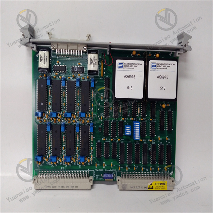
Standard 6U Eurocard flame-retardant PCB with conformal three-proof coating, composed of five core functional units:
- Independent DAC Array Unit: Each channel integrates dedicated 12-bit DAC, high-precision reference voltage circuit, single global potentiometer for gain adjustment, 6 software-selectable voltage ranges.
- Double-Buffered Output Latch Unit: Dual-stage register design supports batch parameter writing + synchronous output refresh via software or external trigger to eliminate multi-loop regulation phase disturbance.
- VME Bus Interface Unit: Compliant with VME Rev.C.1, A24/A32 addressing, DIP switch configurable base address and IRQ1~IRQ7 interrupt priority, two-level bus access permission to avoid multi-board address conflict.
- Signal Conditioning & Protection Unit: Per-channel short-circuit current limiting, ±25V transient overvoltage protection, 0.8Ω low output impedance, ESD/EFT surge protection and front-panel precision reference calibration BNC interface.
- Onboard Diagnosis & Indication Unit: Front-panel status LEDs for power, running and fault alarm; built-in self-test firmware to latch DAC, bus and channel fault information for host diagnosis.
Mounting Specification
Vertical single-slot snap-in installation on standard 19-inch 6U VME rack, compatible with all series of VME master and I/O daughter boards. It has passed IEC anti-vibration, humidity cycling and wide-temperature aging reliability tests with standardized dimensions for direct spare replacement.Dimension (H×W×D): 233.35mm × 160mm × 25mm, net weight: 0.56kg.
Compatible Systems
- Hardware: 6U VME industrial chassis, MVME/VMIVME series SBC, twisted shielded analog cables, high-density terminal adapter boards;
- Software: VxWorks/QNX/Linux real-time OS, VME bus driver, IOWorks configuration tool, DCS/SCADA monitoring software;
- Field Devices: Control valves, servo drives, inverters, excitation regulators, ATE test load equipment;
- Application Industries: Thermal & hydropower plant closed-loop control, substation automation, rail transit vehicle test, aerospace reliability test, chemical & metallurgical process regulation.
Product Characteristics
- Per-channel independent 12-bit DAC with random non-scanning output refresh, maximum 0.03%FS linear error, full-temperature monotonic output to prevent valve oscillation and jitter;
- Six voltage ranges selectable via software, covering single/bipolar industrial standard voltage specifications without hardware modification;
- Hardware offline channel isolation enables independent board calibration without disturbing field equipment, with infinite short-circuit and transient overvoltage protection;
- Automatic full-channel offset & gain calibration corrects temperature and long-term drift, only one global reference potentiometer is needed for coarse adjustment;
- ≥70dB channel crosstalk rejection ensures stable multi-loop simultaneous regulation without signal mutual interference;
- Industrial wide-temperature three-proof design with CE & UL certification for long-term unattended operation in harsh industrial control rooms.
II. Technical Specifications
2.1 Electrical Parameters
- VME Backplane Power: +5VDC, max power consumption 3W, typical operating current 600mA;
- Per-Channel Spec: Max output current ±10mA, output impedance 0.8Ω; voltage ranges: 0~2.5V/0~5V/0~10V/±2.5V/±5V/±10V;
- Dielectric Withstand Voltage: 500VAC/1min between analog channels and ground, per-channel short-circuit & 1s ±25V overvoltage protection, ±4kV ESD, ±2kV EFT surge protection.
2.2 Accuracy & Timing Parameters
- Resolution: 12-bit DAC; INL/DNL ≤0.03%FS (full temperature monotonic);
- Initial Accuracy (25℃): Gain error ±0.03%FS, offset error ±1.5mV;
- Drift: Max gain drift ±35ppm/℃, offset drift ±30μV/℃, long-term drift ≤45ppm/1000h;
- Settling Time: 18μs (full span, 0.01% accuracy), channel crosstalk ≥70dB (DC~1kHz).
2.3 Bus & Channel Parameters
- VME Standard: VMEbus Rev.C.1, A24/A32 addressing, D8/D16/D32 data width;
- Channel Config: 32CH (VMIVME-4140-000) / 16CH (VMIVME-4140-001);
- Output Mode: Single random update / double-buffered synchronous update (software/external trigger);
- Interrupt: Programmable IRQ1~IRQ7 vector interrupt for calibration completion and fault alarm.
2.4 Environmental Specifications
- Operating Temperature: 0℃ ~ +60℃ (standard); Rugged Version: -40℃ ~ +85℃;
- Storage & Transport Temperature: -40℃ ~ +85℃;
- Relative Humidity: 5%~95%RH, non-condensing, no corrosive gas or heavy dust;
- Vibration Standard: IEC 60068-2-6, 0.7g continuous horizontal & vertical vibration;
- EMC Compliance: IEC61000-6-2 industrial electromagnetic immunity standard;
- Protection Class: Bare board IP20, IP30 when installed in sealed metal control cabinet.
2.5 Mechanical Parameters
- Form Factor: Standard 6U VME (233.35mm × 160mm × 25mm);
- Net Weight: 0.56kg;
- Mounting: Vertical snap-in installation on 19-inch VME rack with front anti-loose lock lever;
- PCB: FR4 V0 flame-retardant material with full-area three-proof conformal coating;
- Interfaces: Front analog connector, BNC reference calibration port, status LEDs; rear 96-pin gold-plated VME P1 bus connector.
III. Key Features
3.1 High-Precision Multi-Channel Closed-Loop Analog Control Output
Independent 12-bit DAC converts digital control values into standard industrial voltage signals to drive field actuators for temperature, pressure, flow and load closed-loop regulation. Random single-point refresh and multi-channel synchronous output ensure stable linkage control of multiple process loops and eliminate process disturbance.
3.2 Software Multi-Range Configuration & Automatic Precision Calibration
Six voltage ranges can be switched via software without hardware jumper modification. Automatic power-on or software-triggered calibration compensates full-channel gain and offset errors to maintain long-term output accuracy, and the front-panel reference port supports traceable calibration with external precision standard sources.
3.3 Hardware Offline Channel Isolation & Full-Range Safety Protection
Software-controlled electrical isolation between field wiring and internal DAC circuits enables offline board calibration without interfering running field equipment. Per-channel short-circuit, reverse connection and transient overvoltage protection automatically lock faulty channels to prevent damage to modules and field actuators.
3.4 Double-Buffered Synchronous Output & Flexible VME Multi-Master Networking
Dual-stage latch realizes batch parameter writing and synchronous global output, ideal for multi-valve linkage and synchronous test excitation scenarios. DIP switch configurable address and interrupt support multiple VMIVME-4140 boards working in one VME chassis to expand hundreds of analog control loops for large-scale process systems.
3.5 Power-On Self-Test & Onboard Full-Channel Fault Diagnosis
Comprehensive power, reference voltage, DAC channel and bus communication self-test after power-on latches fault codes and triggers front-panel LED alarm. Runtime overcurrent and communication fault can be actively reported to the host via VME interrupt for rapid equipment troubleshooting and risk disposal.
IV. Working Principle
After VME rack power-on, the host configures the board’s address, interrupt and voltage range; the module executes self-test and automatic channel calibration, then enters ready output mode. Digital control data is written into the first-stage buffer register, and all channels refresh synchronously after trigger command to output analog voltage to field actuators. Faulty channels will be automatically current-limited and locked with interrupt alarm when overloaded or short-circuited. Field circuits can be electrically disconnected via software for offline precision traceable calibration, with compensation parameters saved permanently to maintain long-term output stability.
V. Application Scenarios
- Thermal & hydropower plants: Turbine valve, boiler auxiliary equipment closed-loop regulation and excitation control signal output;
- Substation & captive power plant: On-load tap changer and reactive power compensation analog adjustment control;
- Rail transit vehicle test platforms: Traction & braking system analog excitation reliability testing;
- Aerospace & military ATE equipment: Precision analog stimulus signal generation for sensor and controller performance testing;
- Chemical & metallurgical DCS systems: Reactor temperature & pressure control valve analog regulation;
- Legacy VME industrial control renovation: Direct replacement of faulty AO boards, fully compatible with original chassis, field wiring and bus drivers to reduce upgrade costs.