Description
Performance Characteristics
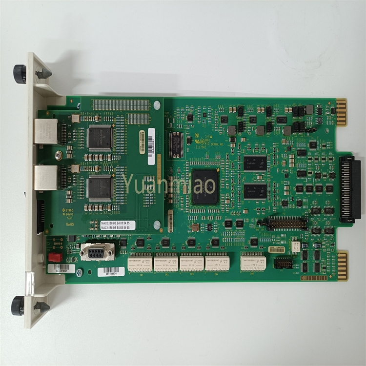
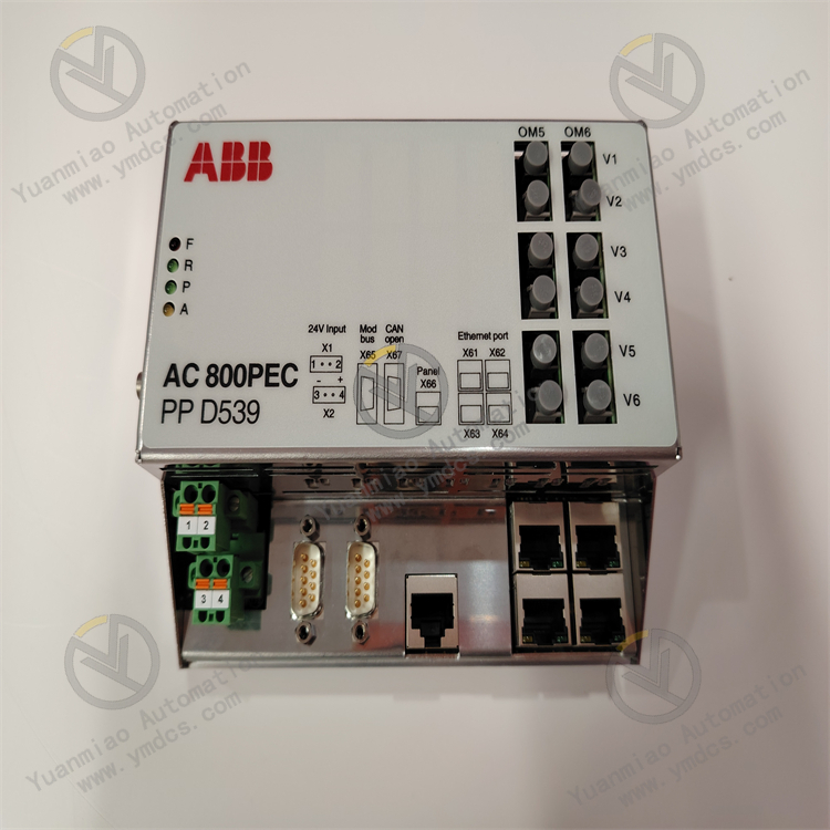
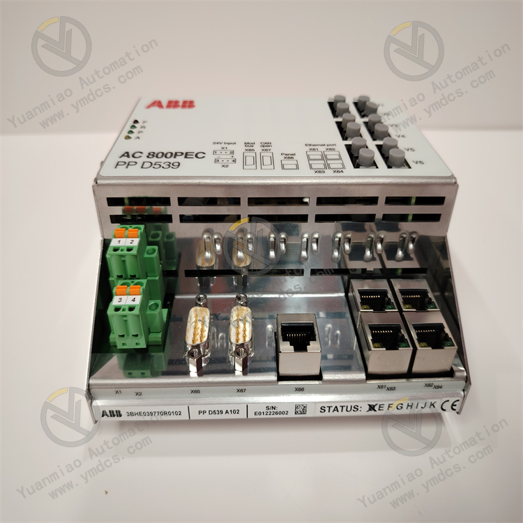
Strong Communication Capability: Supports AC 800 PEC protocol and IEC 61850 communication, enabling efficient and reliable communication with other standard-compliant devices to achieve system integration and collaborative operation.
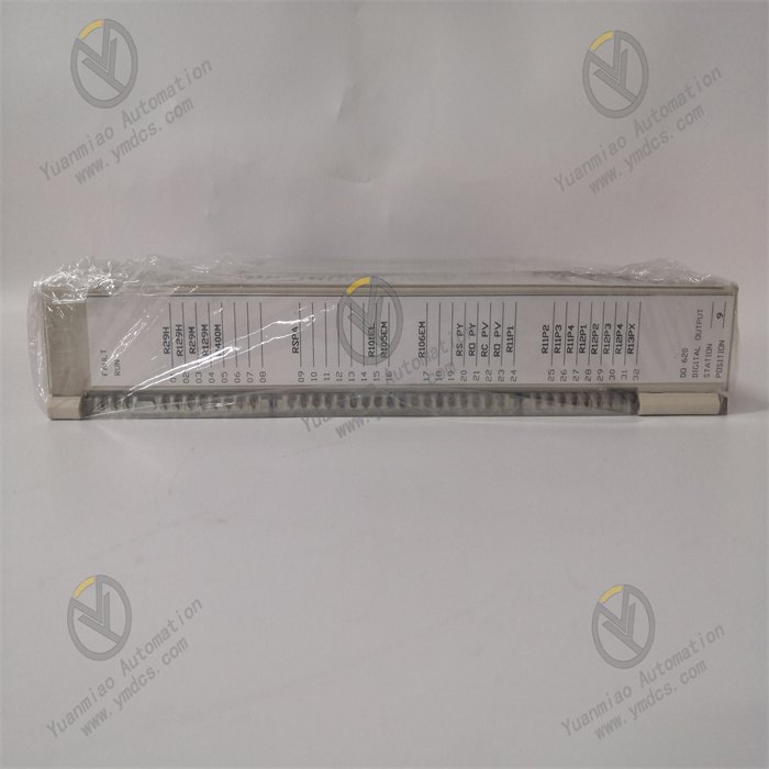
Abundant I/O Interfaces: Equipped with 4 binary inputs, 2 binary outputs, 2 analog inputs, and 1 analog output, allowing convenient connection to external devices such as sensors and actuators for on-site signal acquisition and control.
Self-Detection Function: Features a self-test function that automatically monitors its operational status, promptly detects faults, and triggers alarms, enhancing equipment reliability and stability while reducing maintenance costs.
Convenient Parameterized Configuration: Can be parameterized via AC 800 PEC IEC 61850 SCL files, enabling users to flexibly configure settings according to specific application requirements and reducing on-site debugging time and workload.
Adaptability to Harsh Environments: With a compact and robust design, it operates in harsh environments, featuring a working temperature range of -25°C to +70°C, a storage temperature range of -40°C to +85°C, humidity of 5% to 95% RH (non-condensing), an altitude ≤2000m, and an IP65 protection rating, ensuring stable operation in various industrial environments.
Technical Parameters
Environmental Parameters: Working temperature -25°C to +70°C, storage temperature -40°C to +85°C, humidity 5% to 95% RH (non-condensing), altitude ≤2000m.
Protection Rating: IP65.
Working Principle
Data Acquisition and Processing: Acquires analog and digital signals from external devices (e.g., sensors) through its analog and binary input interfaces, converts and processes these signals into formats recognizable by the internal processor. It then analyzes and judges the processed data based on preset algorithms and logic, such as determining the operating status of motors or abnormal voltage/current in transformers.
Control Output: Sends control signals to external actuators via binary and analog output interfaces based on data processing results to achieve equipment protection and control. For example, when motor overload is detected, it controls relays to cut off the motor power via binary outputs or adjusts the output frequency of inverters via analog outputs to regulate motor speed.
Self-Test Mechanism: The device incorporates a self-test program to periodically detect its hardware and software, such as checking chip status, communication module connections, and data integrity in storage units. Upon detecting faults, it immediately triggers alarm signals through internal mechanisms to notify operators for maintenance.
Operation Guide
Wiring: Correctly connect power supply, input, and output cables according to the device’s wiring diagram. Ensure cable specifications and models comply with requirements, and secure connections to avoid looseness or poor contact. Pay attention to power polarity and voltage consistency with device requirements when connecting the power supply.
Configuration: Establish a connection with the device via its communication port using corresponding configuration software. Open the device’s configuration interface in the software and set parameters (e.g., protection parameters, communication parameters, I/O interface functions) step-by-step as prompted. After configuration, download the configuration file to the device to enable operation with new parameters.
Debugging: After installation, wiring, and configuration, debug the device. First, check power supply normality and indicator lights. Then, test input/output functions by simulating input signals and operating output devices. Use communication tools to verify communication with other related devices. Monitor the device’s operation closely during debugging and troubleshoot any anomalies promptly.
Maintenance: Regularly inspect the device’s operational status, including temperature, noise, and indicator lights, and check for loose or damaged cables. Clean dust and debris from the device’s surface periodically to ensure good heat dissipation. Monitor software versions and update the device’s software and firmware timely to enhance performance, functionality, and address potential vulnerabilities.
Common Faults and Solutions
Abnormal I/O Functions: If input signals cannot be collected or output signals fail to control external devices, potential causes include wiring issues, sensor/actuator faults, or defective I/O modules. Solutions: First check wiring, then test sensors/actuators. If both are normal, the I/O module may be faulty, requiring professional repair or replacement.
Device Overheating: Overheating may occur due to prolonged operation in high-temperature environments or poor heat dissipation. Solutions: Improve heat dissipation conditions (ensure adequate air circulation around the device, clean dust from cooling fans and heat sinks). If unresolved, internal cooling system faults may require maintenance.
Incorrect Parameter Configuration: If device operation deviates from expectations, parameter configuration errors may be the cause. Solutions: Recheck parameter settings to ensure compliance with application requirements, and adjust parameters by referring to the manual or technical documentation.