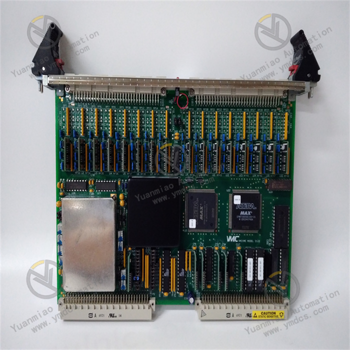
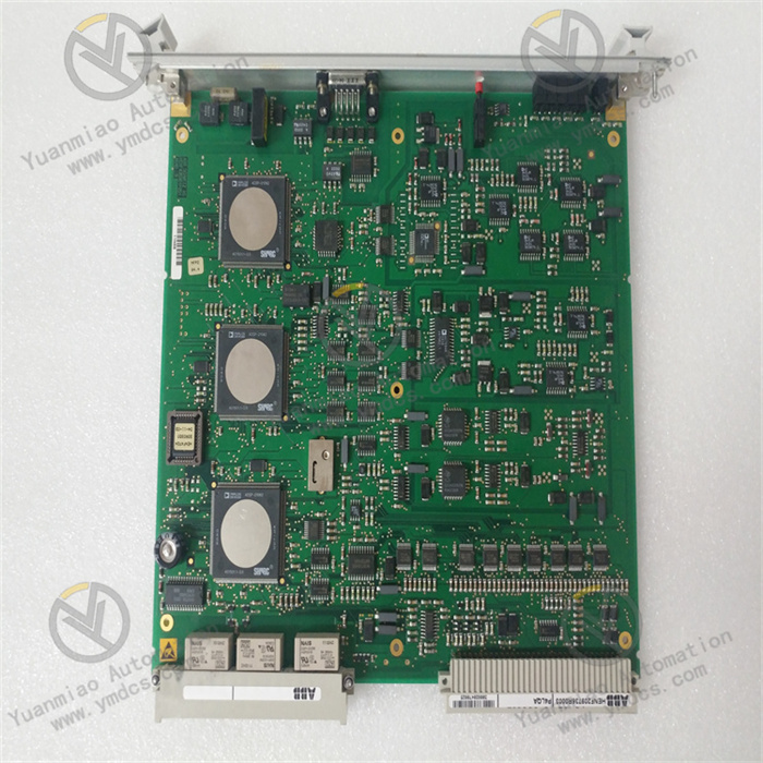
Description
ABB BC810K02 3BSE031155R1
I. Overview
The ABB BC810K02 3BSE031155R1 is a CEX bus interconnection unit kit, with its core positioning as a specialized kit for building redundant communication links in Distributed Control Systems (DCS). Designed specifically for the expansion and interconnection of CEX buses in industrial automation scenarios, this kit enables high-speed data transmission between different modules and controllers within the system. It improves the availability and stability of bus communication through redundant architecture design, and is a key component for constructing high-reliability automation systems.
II. Kit Composition
The BC810K02 3BSE031155R1 kit is a standardized integrated configuration, and each component cooperates to realize the complete CEX bus interconnection function. The specific composition is as follows:
BC810 Interconnection Units: 2 core units, each consisting of a TP857 backplane and a power/logic board. They are responsible for the reception, conversion and interconnection transmission of CEX bus signals, and are the core components for realizing redundant communication and high-speed data interaction.
TP857 Backplanes: 2 adapter backplanes, integrating CEX bus connectors and external power interfaces. They are also equipped with external power voting diodes and fuses, providing installation carriers and power supply protection for the interconnection units. They are grounded with 35mm DIN rails through the metal parts of the housing to enhance anti-interference capability.
TK851 Interconnection Cable: 1 cable with a length of 1.0 meter, specially designed for interconnection between BC810 units. It is used to realize signal synchronization and data transmission of the dual-unit redundant link, ensuring the stability of link connection.
- TB850 CEX Bus Terminators: 2 terminal components, installed at both ends of the CEX bus. They are used to suppress signal reflection, stabilize bus waveforms, ensure the integrity of high-frequency data transmission, and avoid communication abnormalities caused by signal interference.
III. Product Features
Redundant Communication Architecture Support: The kit has built-in dual BC810 interconnection units, which can construct a dual-link redundant communication system and support the configuration of redundant communication interface units. It effectively avoids communication interruption caused by single-link faults, significantly improves the overall reliability and availability of the system, and meets the requirements of uninterrupted operation in industrial scenarios.
Hot-swapping and Online Maintenance: It supports hot-swapping function and online CPU backplane replacement. In a fully redundant system with dual BC810 interconnection and master-slave CPUs, the CPU backplane can be replaced online without interfering with CEX bus communication traffic, minimizing maintenance downtime and ensuring production continuity.
Modular Design for Easy Maintenance: The interconnection unit adopts a split structure of "backplane + power/logic board". The logic board integrates a +3.3V voltage converter, a CEX bus interconnection driver and cable connectors. With a simple structure, it facilitates separate inspection, repair and replacement of components, reducing operation and maintenance costs.
Wide Compatibility and Flexible Expansion: It can be adapted to a variety of controllers in the ABB AC 800M series, including PM857, PM861A, PM862, PM864A, PM891, etc. It can expand communication ports and bus network segments according to the system scale, adapting to automation scenarios of different complexities.
- Powerful Power Supply and Circuit Protection: It adopts 24V DC wide-range power supply, combined with voting diodes and fuses integrated on the backplane. It can effectively resist voltage fluctuations, reverse power supply and other abnormal conditions, protect internal circuits from damage, and enhance power supply stability.
IV. Technical Parameters
| Parameter Name | Specification |
|---|---|
| Product Model | ABB BC810K02 3BSE031155R1 |
| Product Type | CEX Bus Interconnection Unit Kit |
| Compatible Series | ABB AC 800M Series Controllers |
| Power Supply | Nominal 24V DC, voltage variation range 19.2V DC ~ 30V DC |
| Power Consumption | Typical value 50mA, maximum value 70mA at 24V DC; typical power consumption 1.2W |
| Operating Temperature | 5℃ ~ 55℃ (41°F ~ 131°F) |
| Storage Temperature | -40℃ ~ 70℃ (-40°F ~ 158°F) |
| Relative Humidity | 5% ~ 95%, non-condensing |
| Dimensions | 127.5mm (length) × 59mm (width) × 185mm (height) |
| Weight | Single BC810 module: approx. 0.24kg; total weight of the kit including base: approx. 1.4kg; shipping weight: approx. 2.5kg |
| Certification | Compliant with CE standards |
| Interconnection Cable | TK851 type, 1.0 meter long, used for interconnection between dual BC810 units |
V. Working Principle
The core working principle of the ABB BC810K02 3BSE031155R1 kit is a closed-loop process of redundant link establishment - signal conversion and transmission - network segment isolation and optimization - status monitoring and protection. Through the coordinated operation of various components, it achieves high-speed and stable interconnection of the CEX bus. The specific working process can be divided into four core stages:
Stage 1: Link Establishment and Power Supply StartupInstall the 2 BC810 interconnection units on the TP857 backplanes respectively, realize dual-unit interconnection through the 1.0-meter TK851 cable to construct a redundant communication link; install TB850 terminators at both ends of the CEX bus to suppress signal reflection and complete link establishment. The external 24V DC power supply is connected through the backplane interface, and the power supply is distributed through the voting diodes. The fuse provides overcurrent protection for the power supply circuit. Meanwhile, the backplane is grounded through the DIN rail to ensure power supply safety and anti-interference capability.
Stage 2: Signal Conversion and Interconnection TransmissionSignals from external controllers and I/O modules are connected to the BC810 unit through the CEX bus connector. The +3.3V voltage converter on the logic board converts the input voltage into the internal working voltage, drives the CEX bus interconnection driver to work, performs logic conversion and amplification on the signals, and adapts to the bus transmission protocol. The dual units synchronize the communication status through the TK851 cable. When the main link is normal, the master unit is responsible for data transmission, and the standby unit is on standby in real time.
Stage 3: Network Segment Isolation and Redundant SwitchingThe kit can divide the CEX bus into multiple independent network segments, reducing the impact of single network segment faults on the overall system and improving communication availability. When the main BC810 unit or the main link fails, the standby unit immediately detects the abnormality and quickly switches to take over the communication task, ensuring uninterrupted data transmission. The switching process does not interfere with the overall bus traffic, ensuring continuous system operation.
VI. Common Fault Troubleshooting
1. Bus Communication Interruption, Redundant Switching Failure
2. Abnormal Unit Power Supply, Failure to Start Operation
3. Communication Abnormality After Online Replacement of CPU Backplane