Description
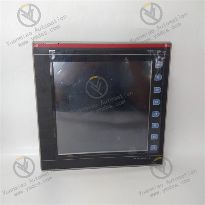
ABB CP450T-ETH 1SBP260189R1001
I. Product Overview
II. Functional Features
Compact Design and User-Friendly Operation Experience
It supports multi-language interface display (including Chinese). The operation interface layout can be customized through the CP400 Soft software, adapting to the operational habits of different industries with low learning costs, facilitating quick mastery by on-site personnel.
Multi-Interface Communication and Wide Compatibility
Supporting network protocols such as TCP, UDP, HTTP, DHCP, and DNS, it enables program upload/download, remote parameter modification, and equipment status monitoring via Ethernet, satisfying both local operation and remote maintenance requirements.
Industrial-Grade Reliable Performance and Environmental Adaptability
It achieves anti-vibration performance of 0.5mm displacement (10-55Hz, 2 hours for each of the XYZ axes) and anti-shock performance of 10g (11ms, 3 times for each axis), capable of withstanding slight vibrations and shocks in industrial sites. Its Mean Time Between Failures (MTBF) meets the requirements of industrial-grade high reliability.
Flexible Programming and Rapid Configuration
It supports touch screen calibration function, which can correct touch deviation through software calibration to ensure operational accuracy. DIP switches are provided for rapid configuration of communication parameters, simplifying the on-site commissioning process.
Full-Scenario Adaptability and High Cost-Effectiveness
III. Technical Parameters
| Category | Specific Parameters |
|---|---|
| Product Type | Compact Industrial Control Panel (HMI), CP400 Series |
| Part Number | 1SBP260189R1001 |
| Model Designation | CP450T-ETH |
| Core Functions | Local operation control, equipment monitoring, parameter configuration, fault alarm, data interaction |
| Display Characteristics | Screen size: 10.4 inches (4:3); Display type: TFT color touch screen; Resolution: 640×480 pixels; Color: 64K colors |
| Operation Method | Resistive touch screen + 7 programmable function keys + 1 menu key |
| Hardware Configuration | Program storage: 8MB ROM; Data storage: 512KB RAM; Real-time clock: Supported |
| Communication Interfaces | Ethernet: 1×10/100Mbps RJ45; Serial ports: 3 (including configurable RS232/RS422/RS485); USB: 1 (for printer/USB flash drive) |
| Supported Protocols | Ethernet/IP, Modbus RTU/TCP, TCP/UDP/HTTP/DHCP/DNS, etc. |
| Power Supply Parameters | Input voltage: 24VDC; Power consumption: Max. 4.8W; Fuse: 1.25A (3.6×10mm) |
| Environmental Adaptability | Operating temperature: 0℃~+50℃; Storage temperature: -10℃~+60℃; Humidity: 20%-90% (non-condensing); Anti-vibration: 0.5mm (10-55Hz); Anti-shock: 10g (11ms) |
| Protection Performance | Front protection: IP65 (NEMA 4X); Rear protection: IP20; Certifications: CE, UL, SAA |
| Physical Parameters | Dimensions (W×H×D): 297mm×222mm×51.6mm; Mounting cutout: 286mm×211mm; Weight: Approx. 1.9kg; Mounting method: Panel mounting |
| Software Compatibility | Programming software: CP400 Soft; Supports multi-language interface, custom recipes, trend chart display |
| Service Life | Complies with industrial-grade long-term operation standards; Touch screen click life ≥ 1 million times |
| Application Scenarios | Small-to-medium automated equipment, standalone control, HVAC, water treatment, machine tools, packaging machinery |
IV. Working Principle
- Local Operation Input: Operators input control commands (e.g., equipment start-stop, parameter modification) via the touch screen or physical function keys, or import recipe parameters via the USB interface. The input signals are processed internally by the panel and converted into standardized control commands.
Command Transmission: Establish a connection with the on-site controller (PLC) via Ethernet or serial communication interface, and transmit control commands and parameter configuration signals to the controller in real time to achieve local command issuance.
- Status Feedback: After executing the commands, the controller sends back data such as equipment running status (e.g., running/stopped, actual parameter values) and fault alarm information to the control panel, forming a closed-loop control system.
- Visual Presentation: The panel intuitively displays the feedback data in the form of numbers, indicator lights, graphics, and trend curves through the preset interface. In case of faults, dual prompts via interface pop-ups and function key indicator lights are provided to facilitate operators in grasping equipment status in a timely manner.
V. Operation Guide
1. Installation Steps
Installation Environment
Mechanical Installation
- Confirm that the equipment model (CP450T-ETH) and part number (1SBP260189R1001) meet the design requirements. Check that the equipment has no appearance damage, the touch screen has no scratches, and the interfaces have no oxidation. Cut a mounting hole on the control cabinet panel according to the mounting cutout dimensions (286mm×211mm), ensuring the edge of the hole is smooth without burrs.
- Embed the equipment into the mounting hole and lock it from the inner side of the panel using the accompanying fixing clips, ensuring the front gasket is tightly attached to the panel (to ensure IP65 protection effect). Reserve ≥ 10cm of wiring and heat dissipation space at the rear of the equipment to avoid blocking communication interfaces and power interfaces.
Wiring Operation
- Turn off the power supply of the control cabinet. Connect the power cable (24VDC positive and negative poles) and communication cables (Ethernet/serial cables) according to the wiring diagram, ensuring firm wiring and correct polarity. If an external printer or data backup is required, connect USB interface devices.
- Use shielded cables for communication lines, with the shield layer grounded at one end (ground resistance ≤ 4Ω). Separate power cables and communication cables with a spacing of ≥ 5cm to avoid electromagnetic interference. If the Ethernet cable length exceeds 100 meters, install a switch to extend the transmission distance.
2. System Configuration
Initialization Settings
- Power on the equipment and observe the panel power indicator light (steady green indicates normal status). The equipment will start automatically and enter the operating system. Configure basic parameters such as system language, date/time, and touch screen calibration via the touch screen initial setup wizard.
- Configure communication parameters via DIP switches or CP400 Soft software: Set Ethernet IP address, serial port baud rate, slave address, etc. Select the communication protocol (e.g., Modbus TCP), establish a communication connection with the controller, and test connectivity (whether data can be refreshed normally).
Interface Deployment
- Install the CP400 Soft programming software on the PC. Design the operation interface according to equipment control requirements, add interface elements such as data display controls, operation buttons, trend charts, and alarm windows, and associate communication variables with controller register addresses.
- Upload the designed interface program to the control panel via USB interface or Ethernet, and the program will run automatically after restarting the equipment. Test the interface functions: Check whether data display is accurate, operation buttons are responsive, function key triggering is normal, and alarm signals are prompted correctly.
3. Operation and Maintenance
Status Monitoring
- Real-time observation of equipment running status: Power indicator light (steady green), Ethernet link indicator light (Link/Activity), function key indicator lights (illuminated when triggered). View communication connection status and data update status via the touch screen status bar.
- Regularly check the consistency between displayed data and actual on-site parameters. If data deviation or non-refresh occurs, troubleshoot the communication link and controller status in a timely manner. Check the touch accuracy of the touch screen; if drift occurs, recalibrate via software.
Regular Maintenance
- Monthly: Wipe the touch screen surface and equipment housing with a dry soft cloth to remove dust and oil stains (avoid using corrosive cleaning agents). Check whether wiring terminals are loose or oxidized; re-tighten loose terminals. Test the stability of the communication link and back up the latest programs and data.
- Every 6 Months: Check the equipment heat dissipation condition and clean dust in the rear interface area. Test the response sensitivity of function keys and the touch screen. Check the stability of power supply voltage (24VDC±10%) to ensure normal power supply. Verify the effectiveness of the fault alarm function.
- Annually: Perform a full-function test and simulate fault signals to verify the alarm mechanism. Update the CP400 Soft software (obtained from official ABB channels). Check the sealing performance of the housing to ensure the IP65 protection rating remains effective.
4. Common Fault Troubleshooting
| Fault Phenomenon | Possible Causes | Troubleshooting Methods |
|---|---|---|
| Equipment fails to start, indicator light not illuminated | Incorrect power wiring, abnormal voltage, blown fuse | Check the polarity of power wiring; measure the input voltage (24VDC) with a multimeter; check if the 1.25A fuse is blown and replace it if necessary |
| Touch screen unresponsive / touch drift | Invalid touch calibration, oil stains/scratches on the surface, hardware failure | Clean the touch screen with a soft cloth; recalibrate via CP400 Soft software; contact after-sales service for testing if the problem persists |
| Communication interruption, data not refreshing | Incorrect communication parameter configuration, faulty communication cable, controller offline | Check parameters such as IP address, protocol type, and baud rate; replace the communication cable for testing; check the controller running status |
| Program cannot be uploaded / run | USB interface failure, incompatible program version, insufficient storage space | Replace the USB interface or flash drive; confirm that the program version is compatible with the equipment; clean redundant files to free up storage space |
| Function keys unresponsive | Unprogrammed function key configuration, key hardware failure | Check the function key configuration in CP400 Soft; test for physical jamming of the keys and contact after-sales service for replacement if necessary |
| Ethernet connection failure | Faulty network cable, IP address conflict, incorrect network settings | Replace the network cable for testing; check for IP address conflicts with other devices; reconfigure subnet mask and gateway |