Description
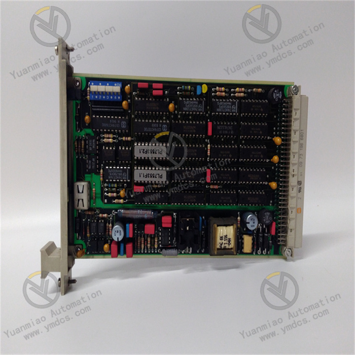
Woodward 8237-1600 Controller
The Woodward 8237-1600 is a microprocessor-based turbine controller manufactured by Woodward, primarily used for controlling various gas turbines. It provides precise control, monitoring, and protection for turbine operations.
Functional Features
- Diverse Control Modes: Supports multiple control modes such as speed control, load control, and combined speed/load control, enabling precise adjustment of turbine operating states according to different application requirements and operating conditions.
- Comprehensive Monitoring and Protection: Real-time monitoring of key turbine parameters (e.g., temperature, speed, load) with safety interlock devices. In case of abnormal conditions, it promptly takes measures to prevent equipment damage and ensure safe turbine operation.
- Convenient Communication Capability: Equipped with communication functions for remote monitoring, control, and data logging, allowing operators to monitor and manage turbines from a distance, enhancing operational convenience and flexibility.
- User-Friendly Interface: Provides an intuitive user interface for easy configuration and operation. Even non-professionals can quickly get started, facilitating parameter setting, function adjustment, and fault troubleshooting.
- Integrated Protection Functions: Features overload protection, undervoltage protection, short-circuit protection, etc., to safeguard the controlled system against abnormalities. It also provides system diagnostics and error reports, enhancing system stability and reliability.
- Strong Durability: Capable of withstanding harsh industrial environments, with robust enclosure options and an extended temperature range (-40°C to +70°C), adapting to various complex industrial scenarios.
Technical Parameters
- Input Voltage: Typically 24V DC, but may vary according to specific system integration.
- Control Inputs: Includes digital inputs (on/off), analog inputs (0-10V, 4-20mA), speed control inputs, etc., capable of receiving multiple signal types to meet different control needs.
- Output Types: Digital and/or analog outputs, configurable as relay outputs, 4-20mA current loops, 0-10V voltage outputs, etc., for flexible connection with various external devices.
- Communication Protocols: Supports multiple communication standards (e.g., Modbus, CAN bus, Ethernet), facilitating integration and data interaction with other control systems.
Application Areas
- Turbine Control: Used in power plants or industrial applications to regulate the operation of gas turbines or steam turbines, ensuring stable and efficient performance to meet power demands in power generation or other industrial processes.
- Engine Control: Manages the performance of internal combustion engines, applicable in power generation, marine applications, and heavy industrial equipment, helping optimize engine efficiency and reliability while reducing energy consumption and maintenance costs.
- Power Generation: Ensures stable operation and load balancing of power plants. Through precise control of turbine or engine output, it enables power plants to adjust power generation in a timely manner according to grid demands, improving the stability and quality of power supply.
- Process Automation: Applicable in chemical plants, refineries, and other industrial processes requiring precise automation and control, providing accurate control of related turbines or engines to achieve automated and optimized production processes and enhance production efficiency and product quality.
- Renewable Energy Systems: Suitable for optimized control of wind turbines, solar inverters, and other renewable energy devices, helping improve the performance and stability of renewable energy equipment and achieve efficient energy conversion and utilization.
General Operation Guide for Woodward 8237-1600
Power-On and Initial Setup
- Power-On Steps: Confirm correct device connections, apply an 18-36 VDC input power supply, turn on the device power switch, and wait for the system self-check to complete. The main interface will be displayed on the screen.
- Initial Setup: Enter configuration mode via front-panel buttons or menu operations. Set basic parameters according to actual application needs, such as control modes (speed control, load control, etc.), input/output signal types and ranges, and turbine-related parameters (rated speed, power, etc.).
Operation Mode Switching
- Configuration Mode: Used for parameter setting and functional configuration of the controller (e.g., adding parameter data). Accessible via specific button combinations or menu options (e.g., pressing the "Mode" key and selecting "Configuration" mode).
- Operation Mode: The normal running mode, in which the controller provides real-time turbine control based on preset parameters. Turbine operating status parameters (e.g., current speed, load, temperature) can be viewed via the operation interface.
- Calibration Mode: Used for calibrating input/output signals, sensors, etc., to ensure measurement and control accuracy. Follow on-screen prompts to complete calibration steps, which may involve calibrating speed sensors, analog input/output signals, etc.
Daily Operations
- Speed Setting: In operation mode, use the "Increase Speed Setpoint" and "Decrease Speed Setpoint" buttons to adjust the turbine's target speed. Speed setpoints can also be received via external analog signals or communication interfaces.
- Load Control: In load control mode, adjust the load setpoint as needed to control turbine output power, achievable via relevant input signals or parameter settings on the operation interface.
- Status Monitoring: Closely monitor turbine operating status information displayed on the screen, including speed, load, temperature, and alarm status. Observe front-panel LED indicators to understand control and hardware status (e.g., green LED indicates normal operation; red LED indicates alarms or faults).
- Alarm Handling: When an alarm occurs, the screen will display alarm information, possibly accompanied by audible prompts. Record the alarm code and relevant details, and perform corresponding fault troubleshooting and handling based on alarm prompts (e.g., check the cooling system for temperature alarms or inspect speed sensors and control parameter settings for speed alarms).
Shutdown Operations
- Normal Shutdown: First adjust the turbine to a safe shutdown state (e.g., reduce speed or load to zero), then select the shutdown option via the operation interface or buttons and turn off the device power.
- Emergency Shutdown: In emergency situations (e.g., abnormal turbine vibration, smoke), immediately press the front-panel "Emergency Trip" button to cut off the turbine's power supply and turn off the device power.

Common Faults and Solutions
Abnormal Speed Control
- Fault Phenomenon: The actual turbine speed does not match the set speed, or speed fluctuations are significant.
- Causes: Faulty speed sensor, improper parameter settings, or control loop interference.
- Solutions: Check the speed sensor connections for looseness or damage, and replace if necessary; reverify speed control parameters to ensure correct settings; inspect control loop wiring to avoid parallel routing with high-power lines and reduce electromagnetic interference.
Unstable Load Control
- Fault Phenomenon: Load cannot stabilize at the set value or fluctuates frequently.
- Causes: Faulty load sensor, issues with the power regulation module, or excessive external load changes.
- Solutions: Test the load sensor's operating status and repair or replace it if faulty; check the power regulation module's output for normal operation and issues like overheating or short circuits; assess external load stability, minimize drastic load changes, or adjust controller parameters to adapt to load variations.
Communication Failures
- Fault Phenomenon: Unable to communicate normally with the host computer or other devices (e.g., Modbus communication interruption).
- Causes: Incorrect communication parameter settings, faulty communication lines, or damaged interfaces.
- Solutions: Confirm that communication parameters (e.g., baud rate, data bits, parity) match those of other devices; check communication lines for damage, breaks, or short circuits, and ensure secure connections; inspect communication interfaces for looseness or oxidation, and replace the communication interface module if necessary.
Frequent Alarms
- Fault Phenomenon: The controller frequently issues alarm signals without obvious actual faults.
- Causes: False sensor triggers, excessively low alarm thresholds, or signal anomalies due to interference.
- Solutions: Check sensor installation positions for correctness and external interference, and calibrate or replace sensors if needed; reassess alarm thresholds and adjust them appropriately; implement anti-interference measures (e.g., adding shielded cables, filters) to eliminate interference signals.
Power Supply Failures
- Fault Phenomenon: The controller cannot start normally, or crashes and reboots occur during operation.
- Causes: Abnormal input power voltage or faulty power supply modules.
- Solutions: Use a multimeter to measure input power voltage, ensuring it falls within the controller's operating voltage range (e.g., 24V DC ±10%), and check power supply line connections for integrity; if the voltage is normal, the power supply module may be damaged, requiring professional maintenance or replacement.