Description
1. Product Overview
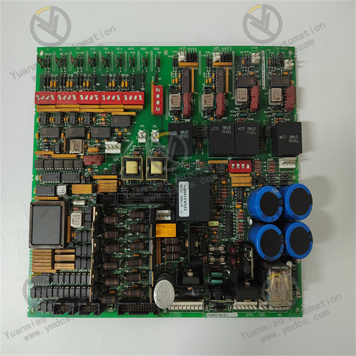
Part Number: DS200DTBDG1A
Manufacturer: General Electric (GE)
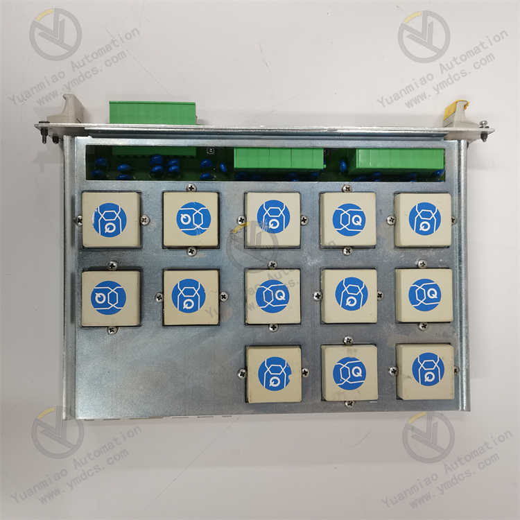
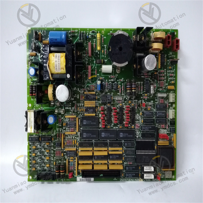
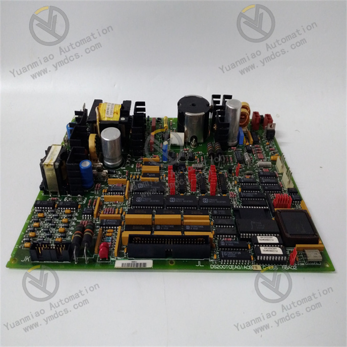
Compatible System: Exclusively designed for GE Speedtronic Mark V turbine control system. It acts as a dedicated terminal base for digital I/O signals, bridging the main processor and field discrete signals. It is the standard signal termination component for ETS trip loops, solenoid valve drive, limit switch feedback, and hard-wired interlock of pressure & temperature switches, supporting direct drop-in replacement of faulty legacy terminal boards.Product Definition: Digital Terminal Board for high-density discrete signal termination. It realizes collection of field digital input dry contact signals and switching of digital output relay contacts. Equipped with opto-isolation, on-board fuses, hardware test points and backplane bus connectors, it converges scattered field wiring into a unified interface connecting to main I/O cards via 34-pin connectors. It eliminates signal interference and wiring faults caused by messy cabling, serving as the essential bottom-layer signal access hardware for combined-cycle thermal power units and industrial drive turbine control systems.
2. Hardware Structure & Six Functional Units
2.1 High-Density Terminal Wiring Convergence Unit
2.2 Opto-Isolated Signal Conditioning Unit
2.3 Branch Circuit Fuse Protection Unit
2.4 Backplane Bus Connector & Jumper Configuration Unit
2.5 On-Board Test Point & Hardware Diagnostic Unit
2.6 Industrial Reinforced PCB & Conformal Coating Protection Unit
3. Detailed Technical Specifications
(1) Core Wiring & Hardware Parameters
| Item | Specification |
|---|---|
| Model | DS200DTBDG1A Digital Terminal Board (DTBD) |
| Compatible System | GE Speedtronic Mark V Gas & Steam Turbine Control System |
| Terminal Layout | 2 terminal blocks, 107 signal terminals per block |
| Core Interfaces | 3 × 34-pin backplane connectors, 2 configuration jumpers, multiple TP test points |
| Supported Signals | Passive dry contact DI input, relay contact DO output termination |
| Isolation | Per-channel optoelectronic galvanic isolation |
| Circuit Protection | Individually replaceable fuse per output channel |
| Fault Logic | Single channel locked upon fuse blow, no impact on remaining board channels |
(2) Electrical Power & Communication Parameters
- Power Supply: Centralized power feeding from Mark V rack backplane
- Rated Voltage: DC 24V ±10%
- Typical Power Consumption: Low power design with minimal heat generation
- Bus Protocol: Native Mark V backplane parallel bus for point-to-point communication with I/O cards
- Hot Swap Restriction: Hot plugging while the rack is energized is strictly prohibited; it will permanently damage backplane ports and on-board isolation chips.
(3) Environmental Parameters
- Operating Temperature: 0℃ ~ +55℃
- Storage & Transport Temperature: -40℃ ~ +70℃
- Humidity: 5%~95%RH non-condensing, no corrosive gas or salt fog deposition
(4) Mechanical Dimensions
- Overall Dimension: 178mm × 149mm × 39mm
- Net Weight: Approx. 0.23kg
- Mounting: Horizontal plug-in fixed installation in standard Mark V rack slots
- PCB Finish: Gold-plated contact traces for oxidation resistance and plug durability
4. Product Advantages
- Large-capacity terminal integration streamlines cabinet wiring and eliminates intermediate marshalling links to reduce wiring faults such as poor contact and short circuits.
- Dual protection of opto-isolation and branch fuses prevents external field faults from damaging core control cards, limiting fault scope to individual loops only.
- Hardware jumper configuration enables flexible address assignment, allowing direct drop-in replacement in any compatible rack slot without program modification to shorten unit outage maintenance time.
- On-board test points support in-situ circuit verification without cable removal to accelerate fault localization and reduce maintenance difficulty.
- Full native compatibility with Mark V system hardware pinout and bus protocol enables plug-and-play replacement for legacy equipment without additional commissioning or calibration.
- Fanless maintenance-free design with conformal coating withstands harsh industrial ambient conditions and requires only periodic inspection during unit overhauls with minimal routine upkeep.
5. Application Scenarios
Thermal Power Combined-Cycle Power Generation
Petrochemical Process Power Industry
Legacy Control System Retrofit
Preventive Spare Part Inventory