Description
1. Product Overview
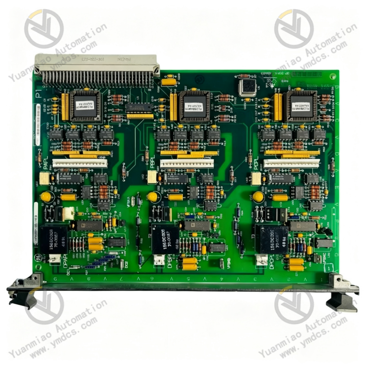
Part Number: IS200BPIBG1AEB, base part IS200BPIBG1A. Suffix EB indicates finalized PCB revision, transformer parameter calibration and factory full inspection batch. No cross-model hardware compatibility; only identical suffix spares support direct drop-in replacement.
Manufacturer: General ElectricSystem Affiliation: Core signal conditioning and fault interlock VME plug-in card for Speedtronic Mark VI / Mark VIe gas & steam turbine high-power variable-frequency drive control systems, Only factory surplus, refurbished and project redundant spares are available for procurement. It serves as the upper-layer logic core of inverter power units and medium-voltage variable-speed loops.Model Coding Definition
- IS200: Unified prefix for IS200 series VME cards of Mark VI control system;
- BPIB: Abbreviation of Bridge Personality Interface Board;
- G1: 1st generation hardware architecture;
AEB: Final revision of PCB layout, transformer secondary winding parameters and pinout definition.
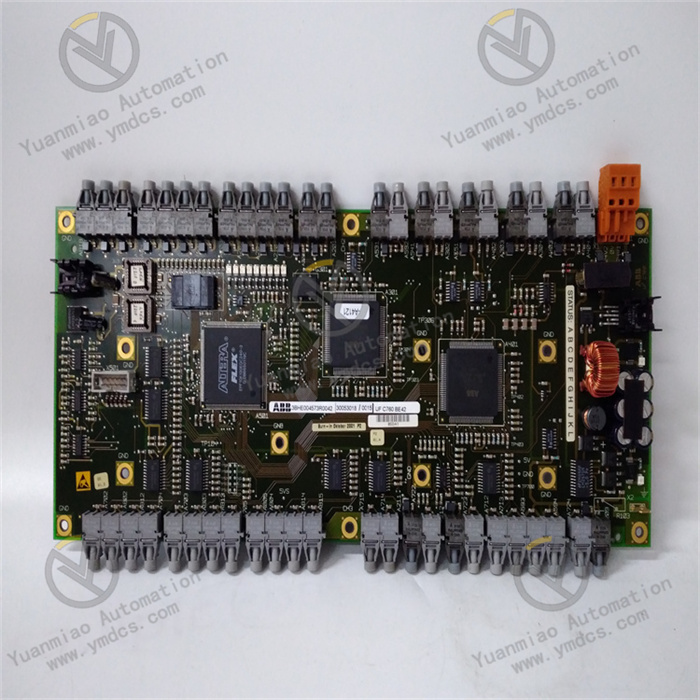
Product Definition: The central logic board of power inverter units, which receives bridge arm drive commands from VME rack main controller, executes opto-isolation, level conversion and phase-based drive signal distribution. It samples DC link voltage, three-phase bridge output voltage and IGBT gate driver fault signals, generates VCO frequency feedback and uploads to main control. Each phase adopts independent hardware fault latch to prevent shoot-through short-circuit of IGBTs. It integrates command forwarding, status acquisition, fault interlock and feedback transmission as the core interface of high-power inverter units.
2. Six Core Hardware Functional Units
2.1 Isolated Signal Conditioning & Command Distribution Unit
2.2 DC Link & Phase Voltage VCO Feedback Sampling Unit
2.3 Phase-Isolated Fault Latch & Alarm Reporting Unit
2.4 Multi-Channel Isolated Auxiliary Power Generation Unit
2.5 Total Bus Overcurrent Shunt Signal Aggregation Unit
2.6 Industrial Reinforced Environmental Adaptation Unit
3. Technical Specifications
3.1 Basic Hardware Specifications
| Item | Specification |
|---|---|
| Full Part Number | IS200BPIBG1AEB |
| Card Type | Mark VI VME 6U plug-in BPIB bridge interface board |
| Mounting | Standard 6U VME vertical slot installation with front latch anti-loosening |
| Main Interfaces | Rear P1 VME bus connector, three-phase signal terminals, driver cable ports, AC power input |
| Dimension | Standard 6U VME size: 233.35mm × 160mm |
| Net Weight | Approx. 0.42kg |
3.2 Core Electrical Parameters
- Primary Input Power: 17.7VAC square wave; Logic Supply: 5VDC from backplane
- Output for Driver Boards: Isolated 5VDC, rated 500mA
- VCO Feedback Frequency Range: 0 ~ 20MHz linear voltage-frequency conversion
- Dielectric Withstand Voltage: 2500VAC 1min isolation between main control logic and power drive side
- Controlled Bridge Arms: 3-phase full bridge with upper/lower IGBT drive per phase
- Fault Reset Mechanism: Hardware latched fault, only clearable via system software reset
- Isolation Level: Dual redundant optocoupler isolation per control channel
3.3 Environmental & Compliance Standards
- Operating Temperature: 0℃ ~ +65℃
- Storage & Transport Temperature: -40℃ ~ +85℃
- Humidity: 5%~95%RH non-condensing, no corrosive gas or salt fog deposition
- Ingress Protection: IP20, for installation only inside sealed industrial control cabinets
4. Product Advantages
- Hardware-priority fault protection: Drive output blocking is implemented via pure hardware latch independent of CPU software. Protection remains effective even under system crash or communication loss to prevent catastrophic damage such as IGBT shoot-through and DC link capacitor explosion.
- Three-level isolation architecture: Optocoupler + transformer double isolation between backplane weak current, intermediate signal stage and power strong current stage. Short circuit and surge on power side cannot damage VME rack main control CPU and backplane.
- All-in-one integration of power supply, sampling, drive distribution and fault reporting: Replaces multiple discrete boards to reduce cabinet component count and wiring fault points.
- Dual redundant optocoupler signal transmission: Single optocoupler failure will not cause complete loss of drive signal, improving long-term stability of variable-frequency continuous production units.
- Frequency-based DC link feedback: Analog voltage converted to frequency signal for long-distance transmission with far superior anti-interference performance compared to conventional 4~20mA analog cables.
- Strict model restriction for replacement: IS200BPIBG1A base version cannot substitute AEB revision due to fixed transformer ratio and VCO parameters. Direct replacement requires no modification to unit control logic after installation.
5. Application Scenarios
1. GE 6FA/9FA Gas Turbine Mark VIe Starter Variable-Frequency System
2. Auxiliary High-Voltage Variable-Frequency Systems of Thermal Power Steam Turbines
3. Large Reciprocating Compressor Variable-Frequency Drives in Petrochemical Industry
4. Excitation Power Units of Waste Heat & Captive Power Plant Steam Turbines