Description
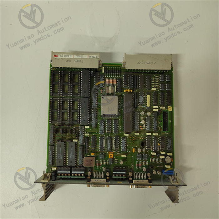
ABB PMA323BE HIEE300308R1
ABB PMA323BE HIEE300308R1 is a multifunctional industrial control module, compatible with the Freelance distributed control system simultaneously. Integrating process control, machine control, data acquisition, stable power supply and multi-protocol communication in one, it is specially designed for small and medium-sized industrial automation scenarios. Its core functions cover logic control, analog/digital signal conversion, cross-device data interaction and system stable power supply. Through mainstream industrial protocols such as Modbus and Profibus, it achieves seamless integration with on-site sensors, actuators and upper computer systems, providing an efficient and reliable integrated control solution for fields including industrial automation, energy management, water treatment, building automation, metallurgy and petrochemicals.
Adopting an industrial-grade modular design, this module features both high-performance computing capability and high-stability power supply characteristics. It supports convenient DIN rail installation and flexible expansion. With multiple protection mechanisms such as overcurrent, overvoltage and overheating protection, as well as strong adaptability to harsh environments, it serves as a key hub connecting on-site equipment and upper monitoring systems, ensuring the continuous and stable operation of industrial processes.
- Equipped with a high-performance microcontroller, it supports the execution of complex control algorithms and can process logic control, process regulation, data acquisition and signal conversion tasks in parallel. It is compatible with digital/analog input and output, suitable for real-time monitoring and control of various parameters such as temperature, pressure and flow.
- Built-in 16MB PROM memory supports control program storage and offline operation, with fast computing response, meeting the real-time control requirements of small and medium-sized industrial systems (such as production line beat control and equipment start-stop logic).
- It supports multiple programming languages and development environments. Combined with ABB dedicated programming tools, it simplifies the development, debugging and modification process of complex control logic, adapting to the needs of rapid project implementation.
- Integrated with a high-performance power supply unit, the input voltage supports 24VDC (compatible with 220VAC wide voltage input in some scenarios), the output voltage is stably 24VDC, the maximum output current can reach 30A, and the power capacity is 720W, which can provide continuous and stable power supply for itself and associated control modules.
- The power conversion efficiency is >90%, and the ripple and noise are <10mV, ensuring that the control signal and power supply quality are not interfered with. It has a 150% overload capacity and supports multiple protections including overcurrent, overvoltage, short circuit, overheating and undervoltage protection. In case of faults, it will automatically cut off the output to avoid equipment damage.
- Selected industrial-grade components and sealed protection design (IP20), the operating temperature range is -20℃~+60℃ (adaptable to -40℃~70℃ in extreme environments), the humidity adaptability range is 5%-95% (no condensation), with strong anti-electromagnetic interference capability, suitable for harsh industrial scenarios with high dust and high humidity.
- Natively supports mainstream industrial communication protocols such as Modbus, Profibus and RS485. It can be directly integrated with ABB Advant Controller 250 series controllers, Freelance DCS systems, as well as third-party PLCs and intelligent instruments without additional protocol gateways.
- Reserved Fieldbus hardware interface supports future system expansion. The unified parameter configuration and programming of PA standard instruments can be realized by importing device GSD files, reducing software costs and engineering configuration complexity.
- It is downward compatible with underlying equipment such as on-site sensors and actuators, and seamlessly connects with upper monitoring systems upward, supporting production data upload and remote control command reception, facilitating the digital transformation of industrial automation and energy management.
- Adopting a modular and compact design, with dimensions of only 120×80×40mm and a weight of about 500g, it supports quick DIN rail installation, saving control cabinet space. The module supports hot swapping (in some scenarios), so maintenance does not require overall shutdown, reducing production downtime.
- It supports expanding I/O channels and functions by adding expansion modules, adapting to control requirements of different scales. The front panel is equipped with status indicators, which can intuitively display power status, operation status and fault alarms, facilitating quick on-site troubleshooting.
- Combined with dedicated configuration software, it supports remote programming, parameter modification, program backup and firmware upgrade, as well as device operation log query, reducing on-site maintenance workload and costs.
- Core functions cover: data acquisition (on-site parameters such as temperature, pressure and flow), logic control (equipment linkage and process logic execution), signal conversion (bidirectional conversion between analog and digital quantities), stable power supply (supplying power for itself and associated modules), and communication transfer (data interaction between underlying equipment and upper systems).
- Suitable for multi-field applications: industrial automation (factory production lines and conveying systems), energy management (energy consumption monitoring of electric power, petroleum and natural gas), process control (closed-loop regulation of temperature/flow), machine control (robot and packaging machine automation), and infrastructure (water treatment and building automation).
The core working logic of ABB PMA323BE HIEE300308R1 follows the sequence of "stable power supply → data acquisition → logic operation → control output → communication interaction → fault protection", with the specific process as follows:
Stable Power Supply: It receives 24VDC (or 220VAC) power through the input interface. After being processed by the high-efficiency power conversion unit, it outputs stable 24VDC power to supply power for itself, expansion modules and associated on-site equipment. Meanwhile, it real-time monitors the power supply status through the protection circuit and triggers the protection mechanism in case of abnormalities.
Data Acquisition: It receives analog/digital signals from on-site sensors (such as temperature and pressure data) through the built-in I/O interface, or receives operation data from third-party devices via Modbus/Profibus protocols, realizing unified access and preprocessing (filtering and signal conversion) of multi-source data.
Logic Operation: The microcontroller performs logical judgment and control algorithm operation (such as simple PID regulation) on the collected data according to the preset control program (programmed by dedicated software), and generates control commands and status feedback information.
Control Output: The processed control commands are output to actuators (valves, motors, etc.) through the I/O interface to realize operations such as equipment start-stop and parameter adjustment. At the same time, it feeds back the equipment operation status and control results to the local indicators and upper systems.
Communication Interaction: It performs data interaction with upper monitoring systems and third-party devices through the communication interface, uploading collected data, operation status and fault information, receiving remote control commands and parameter configurations, and realizing cross-device collaborative control.
- Fault Protection: It real-time monitors the power supply voltage, output current, module temperature and communication status. When abnormalities such as overcurrent, overvoltage, short circuit and overheating are detected, it immediately cuts off the output power and triggers an alarm, and uploads fault codes at the same time to ensure system safety.
Install on a standard DIN rail, away from strong electromagnetic interference sources such as frequency converters and high-voltage cables. Reserve a heat dissipation gap of ≥10mm on both sides. The control cabinet must ensure good ventilation to avoid the ambient temperature exceeding the range of -20℃~+60℃.
- Confirm that the main power supply of the control cabinet is cut off. Fasten the module on the DIN rail with the buckle until the buckle is locked to ensure firm installation without loosening. When multiple modules are installed side by side, the spacing should be ≥5mm to avoid poor heat dissipation.
- If expansion modules are configured, connect them in the order of "main module → expansion module", ensure that the communication interfaces between modules are properly connected, and lock the fixing screws.
- Power Wiring: Connect the input power supply according to the mark to 24VDC (or 220VAC, need to confirm the module specification), strictly distinguish positive and negative poles/phase and neutral lines, and fasten the wiring terminals. It is recommended to connect a 3A (24VDC) or 10A (220VAC) fuse in series on the input side, and use 1.5mm² copper core cables for power lines.
- Communication Wiring: Connect the RS485/Profibus interface to the bus according to the "positive to positive, negative to negative" principle, and ground the shielding layer at one end (grounding resistance ≤4Ω). When the Fieldbus expansion interface is reserved, do a good job of interface protection to avoid dust entering.
- Notes: Before wiring, confirm that the power supply voltage matches the rated input of the module, and reverse polarity connection is prohibited. Route communication cables separately from power cables (spacing ≥15cm) to reduce electromagnetic interference.
- Install ABB dedicated programming and configuration software, establish a connection with the module through the communication interface, create a project and select the PMA323BE HIEE300308R1 model, and configure communication protocols (such as Modbus slave address and Profibus station number), I/O signal types, power output parameters, etc.
- Programming and Logic Configuration: Write control logic using supported programming languages, define data acquisition addresses, control thresholds and fault response strategies. Import GSD files of third-party devices to complete parameter configuration and association of PA instruments.
- Before the first power-on, verify the correctness of wiring and the consistency between the module model and configuration parameters. Use a multimeter to detect whether the input voltage is within the allowable fluctuation range.
- After power-on, observe the front panel indicators: the steady power indicator and flashing running indicator indicate normal operation; if the fault indicator is steady on, read the fault code (such as overcurrent and overvoltage alarm) through the software to troubleshoot wiring or load problems.
- Function Test: Simulate input sensor signals to verify the accuracy of data acquisition; force output control commands to observe whether the actuator actions meet expectations; test the stability of power output, and use an oscilloscope to detect whether the ripple and noise are <10mV.
- Communication Test: Verify the communication connection between the module and the upper computer as well as third-party devices to ensure no packet loss in data transmission; test the functions of remote parameter modification and program download to confirm that remote operation and maintenance are normal.
Real-time monitoring through the upper monitoring system or local indicators:
- Normal Status: Stable power supply, flashing running indicator, no fault alarm, output voltage/current within the set range, and unobstructed communication link.
- Fault Status: The fault indicator is steady on, and the upper computer displays fault codes (such as overload and overheating). It is necessary to check the load or ambient temperature immediately.
- Monthly: Clean dust on the module surface and interfaces with dry compressed air, check the installation firmness and whether the wiring terminals are loose or oxidized; view the operation log through the software to confirm no abnormal alarms.
- Every 6 Months: Conduct a comprehensive inspection of the insulation layer of power cables and communication cables for damage, and check the reliability of shielding layer grounding; back up control programs and configuration parameters; test the effectiveness of protection functions (such as simulating short circuit to verify whether the output is automatically cut off).
- Annually: Check whether the internal components of the module have signs of aging (such as swollen capacitors); upgrade the configuration software and module firmware to the latest stable version; calibrate the accuracy of data acquisition and output to ensure control reliability.
![]()