Description
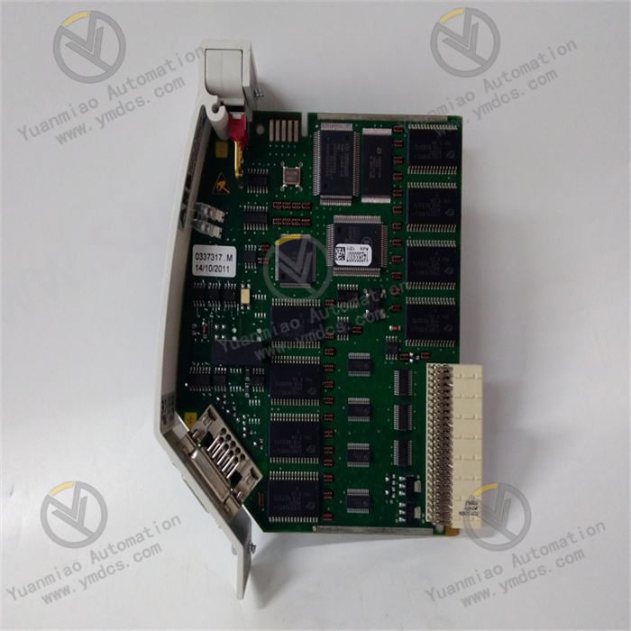
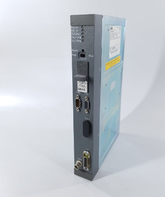
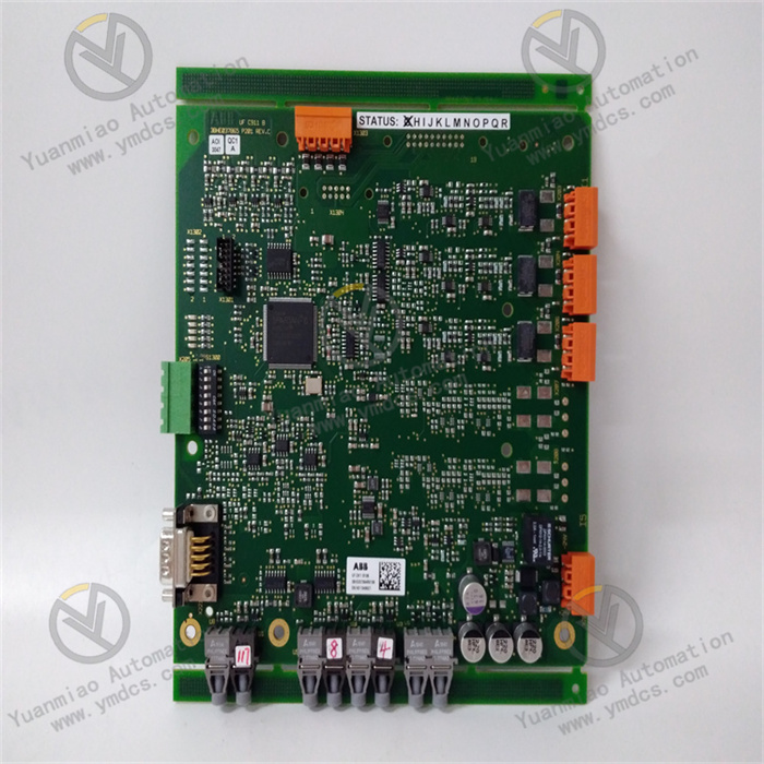
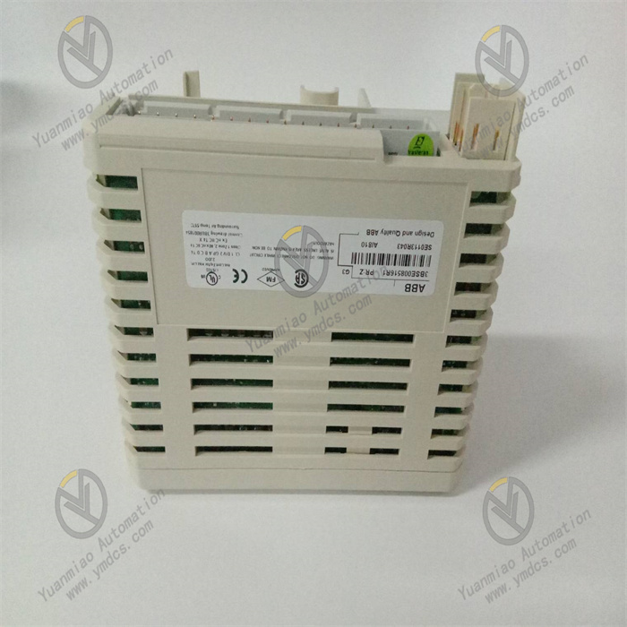
ABB AI825 3BSE036456R1
I. Product Overview
ABB AI825 3BSE036456R1 is an isolated analog input module belonging to the S800 I/O series. Its core function is to collect analog signals (current/voltage type) output by industrial field sensors (such as pressure, temperature, and flow sensors). After undergoing isolation conversion and precision filtering, these signals are transmitted to the DCS/PLC main controller, providing high-reliability data support for industrial process control.
Designed specifically for complex industrial environments, this module features a 4-channel independent electrical isolation design, achieving 250V isolation voltage between channels and between channels and ground. It is fully compatible with mainstream control systems such as ABB 800xA and Symphony Plus. With 14-bit high resolution, ±0.1% measurement accuracy, wide signal range adaptability, and industrial-grade anti-interference performance, it is widely used in fields including petrochemicals, power generation, intelligent manufacturing, water treatment, and food processing, serving as a core component to ensure precise monitoring and control of industrial processes.
II. Functional Features
4-Channel Independent Isolation and Multi-Signal Adaptability
- Equipped with 4 independent electrically isolated channels (isolation between channels and between channels and ground) with an isolation voltage of up to 250V, effectively avoiding signal crosstalk and external interference. It is suitable for scenarios where multiple sensors collect data simultaneously, improving the stability of data acquisition.
- Supports a variety of standard analog signal inputs: current signals (-20~+20mA, 0~20mA, 4~20mA) and voltage signals (-10~+10V, 0~10V, 2~10V). Each channel can be independently configured for signal types, adapting to different types of sensors without additional modules, and flexibly meeting the diverse measurement needs of industrial sites.
High-Precision Acquisition and Low-Drift Characteristics
- Boasts a measurement accuracy of ±0.1% and a resolution of 14 bits plus sign bit, enabling accurate capture of tiny signal changes. It is ideal for high-precision industrial measurement scenarios (such as precision pressure control and micro-flow monitoring).
- Features excellent temperature stability, with a maximum temperature drift of 57ppm/℃ for current signals and 34ppm/℃ for voltage signals. It maintains consistent measurement accuracy within the wide temperature range of -25℃~+70℃, preventing environmental temperature changes from affecting data accuracy.
Industrial-Grade Anti-Interference and Safety Protection
- Adopts enhanced Electromagnetic Compatibility (EMC) design, with a Common Mode Rejection Ratio (CMRR) of 120dB (50/60Hz) and a Normal Mode Rejection Ratio (NMRR) of >55dB (60Hz). It can resist complex interferences in industrial sites such as high-frequency electromagnetic radiation and power grid fluctuations, ensuring distortion-free signal transmission.
- Built-in overvoltage protection mechanism: current input channels can withstand a maximum DC overvoltage of 30V, and voltage input channels can withstand a DC overvoltage of 6.3V. Combined with PTC resistor current-limiting design, it effectively protects the module from impacts such as sensor wiring errors and power supply abnormalities, extending service life.
- Supports HART communication tolerance; input channels can be directly connected to sensors with HART protocol without additional isolators, simplifying the system architecture.
High Reliability and Environmental Adaptability
- Utilizes industrial-grade high-stability components and sealed protection design (IP20). It operates within a temperature range of -25℃~+70℃ and a humidity range of 5%-95% (non-condensing), enabling long-term stable operation in harsh industrial environments with high temperature, high humidity, and heavy dust, and delivers excellent Mean Time Between Failures (MTBF) performance.
- Powered by the module bus (24V), the input-stage power supply is isolated through internal conversion, featuring low power consumption (typically 2.5W, maximum 3.2W). It is energy-efficient and environmentally friendly, reducing heat dissipation pressure, and is suitable for high-density cabinet installation scenarios.
Easy Integration and Maintenance
- Seamlessly compatible with ABB 800xA, Symphony Plus control systems and the S800 I/O series backplane bus. It supports matching use with terminal units such as TU811, TU813, and TU831, and is automatically recognized by the system after installation without complex protocol configuration.
- Adopts a compact design (45mm in width, 102mm in depth, 119mm in height) with a weight of only 0.22kg, suitable for standard industrial rail installation, saving cabinet space. Channel configuration is completed through system software without on-site jumpers, facilitating maintenance.
III. Technical Parameters
| Category | Specific Parameters |
|---|---|
| Product Type | High-precision isolated analog input module of the S800 I/O series |
| Core Functions | Analog signal acquisition, isolation conversion, filtered transmission, fault self-monitoring |
| Channel Configuration | 4 channels, independent electrical isolation between channels and between channels and ground |
| Input Signals | Current: -20~+20mA, 0~20mA, 4~20mA; Voltage: -10~+10V, 0~10V, 2~10V |
| Measurement Accuracy | ±0.1% (at 25℃) |
| Resolution | 14 bits + sign bit |
| Input Impedance | Voltage input: 10MΩ; Current input: 50Ω (standard), 50Ω+125Ω (overvoltage protection) |
| Anti-Interference Performance | CMRR: 120dB (50/60Hz); NMRR: >40dB (50Hz), >55dB (60Hz) |
| Protection Features | Overvoltage protection: 30V DC for current channels, 6.3V DC for voltage channels; PTC resistor current limiting |
| Transmission Performance | 4-channel update cycle < 10ms; Input filtering time: 130ms for current channels, 115ms for voltage channels (0~90%) |
| Power Supply Parameters | Supply voltage: 24V DC (module bus); Current consumption: typical 90mA (max 110mA) at 24V, typical 70mA (max 100mA) at 5V |
| Physical Parameters | Dimensions: 45mm (W) × 102mm (D) × 119mm (H); Weight: approx. 0.22kg |
| Environmental Adaptability | Operating temperature: -25℃~+70℃; Storage temperature: -40℃~+85℃; Humidity: 5%-95% (non-condensing); Protection class: IP20 |
| Compatible Systems | ABB 800xA, Symphony Plus, S800 I/O series; Compatible with terminal units TU811/TU813/TU831 |
| Application Scenarios | Petrochemicals, power generation, intelligent manufacturing, water treatment, food processing, precision pressure/flow monitoring |
IV. Working Principle
The core working logic of ABB AI825 3BSE036456R1 is "signal acquisition → isolation and filtering → analog-to-digital conversion → data transmission → status monitoring", with the specific process as follows:
Signal Acquisition: Analog signals (current/voltage) output by industrial field sensors are connected to corresponding channels through terminal units (e.g., TU813). The module supports field cable connections of up to 600 meters, suitable for long-distance measurement scenarios.
- Isolation and Filtering: Input signals are isolated by channel-independent isolation circuits to avoid external interference and channel crosstalk. Then, high-frequency noise is filtered out through low-pass filter circuits to ensure signal stability. The filtering time can be automatically adapted according to the signal type (130ms for current channels, 115ms for voltage channels).
Analog-to-Digital Conversion: Filtered analog signals are sent to a 14-bit high-precision ADC converter and converted into digital signals with a conversion accuracy of ±0.1%, ensuring that tiny signal changes are accurately captured.
- Data Transmission: Digital signals are transmitted to the main controller through the S800 I/O backplane bus, with a 4-channel synchronous update cycle of < 10ms, meeting the low-latency requirements of industrial real-time control for data transmission.
- Status Monitoring: The module real-time monitors its own power supply status and channel signal integrity. When abnormalities such as overvoltage and signal overrange are detected, it automatically uploads fault information to the controller for quick troubleshooting.
V. Operation Guide
1. Installation Steps
Installation Environment
Install in an S800 I/O standard control cabinet, away from strong electromagnetic interference sources such as frequency converters and high-voltage cables. Reserve a heat dissipation gap of ≥10mm on both sides; the control cabinet must be equipped with ventilation functions to prevent the ambient temperature from exceeding the range of -25℃~+70℃.
Mechanical Installation
- Ensure the main power supply of the control cabinet is cut off. Align the module with the S800 I/O series standard rail, push it in and lock it with the buckle to ensure the module is firmly attached to the rail without loosening.
- If matching with a terminal unit (e.g., TU813), install the terminal unit first, then accurately dock and lock the module with the terminal unit.
- When installing multiple modules, maintain a spacing of ≥15mm between modules to avoid mutual interference, and reserve space for wiring and maintenance.
Wiring Specifications
- Signal Wiring: Connect sensor signal wires according to the terminal markings of the terminal unit. Use two-wire/four-wire wiring for current signals and differential wiring for voltage signals. Select shielded twisted-pair cables, with the shield layer grounded at one end (ground resistance ≤4Ω), and the cable length should not exceed 600 meters.
- Notes: Before wiring, confirm that the sensor signal type is consistent with the channel configuration to avoid reverse polarity connection. In overvoltage environments, additionally check the integrity of the cable insulation layer to prevent short circuits from damaging the module.
2. Configuration and Commissioning
Parameter Configuration
- Connect to ABB programming software (e.g., Control Builder Plus, 800xA Engineering). Add the AI825 module in the system configuration interface, configure the signal type (current/voltage) and input range (e.g., 4~20mA, 0~10V) for each channel, set the signal filtering mode and fault response strategy (e.g., overrange alarm), save the configuration and download it to the main controller.
- When connecting to sensors with HART protocol, no additional configuration is required; the module can directly tolerate HART communication signals without affecting analog signal acquisition.
Power-On Commissioning
- Before the first power-on, verify the correctness of wiring, consistency between the module model and configuration parameters, and confirm there are no issues such as short circuits or reverse connections. Use a multimeter to test the sensor output signal to ensure it is within the configured range.
- After powering on, observe whether the module is correctly recognized by the system without fault alarm prompts. If a communication fault occurs, check the reliability of the connection between the module and the backplane bus.
- Accuracy Test: Input standard signals (e.g., 4mA, 20mA current signals, 0V, 10V voltage signals) to each channel, read the measured values through the upper software, and verify that the measurement accuracy is within the range of ±0.1%. Test the response speed when the signal changes abruptly to ensure there is no significant delay.
- Interference Test: Start interference sources such as frequency converters near the module, observe the stability of the measured data, and verify the anti-interference performance.
3. Operation and Maintenance
Status Monitoring
Real-time monitor the module operation status through the upper monitoring system:
- Normal Status: No fault alarms on the module, measured data is stable within a reasonable range, and channel signals have no obvious fluctuations.
- Fault Status: The system displays fault codes (e.g., overvoltage fault, signal overrange), which need to be troubleshooted in combination with wiring and sensor status.
Regular Maintenance
- Monthly: Clean dust on the module surface and interfaces with dry compressed air, check the firmness of module installation and whether the wiring terminals are loose or oxidized. View the trend of measured data through software to ensure there is no abnormal drift.
- Every 6 Months: Conduct a comprehensive inspection of the signal cable insulation layer for damage or aging, and check the reliability of shield layer grounding. Calibrate the measurement accuracy of sensors and modules, verify the channel error through a standard signal source to ensure it is ≤±0.1%, and back up the module configuration parameters.
- Annually: Inspect internal components of the module for signs of aging (e.g., bulging capacitors). If the module experiences reduced measurement accuracy or frequent alarms, replace it with original spare parts in a timely manner.
Notes
- Wiring, parameter configuration, and module insertion/removal must be performed with the power off. Live operation is prohibited to avoid short circuits or module damage.
- Do not use the module beyond the channel input range. For example, avoid connecting voltage signals exceeding 30V to current channels to prevent triggering overvoltage protection or burning the internal circuit.
- For modules that have been idle for a long time (more than 6 months), conduct an insulation test (using a 500V megohmmeter, with insulation resistance ≥10MΩ) and functional verification before use, and connect them to the system only after confirming there are no abnormalities.
4. Common Fault Troubleshooting
| Fault Phenomenon | Possible Causes | Troubleshooting Methods |
|---|---|---|
| Large deviation in measured data | Incorrect signal wiring, mismatched channel configuration, sensor failure | Verify wiring method and polarity; confirm that the channel signal type configuration is consistent with the sensor; test the sensor output accuracy independently |
| Severe fluctuation of data | Electromagnetic interference, ungrounded shield layer, excessively long cables | Strengthen shield layer grounding; shorten cable length (≤600m); replace with high-quality shielded twisted-pair cables; keep away from interference sources |
| No data output from the module | Unrecognized module, loose bus connection, abnormal power supply | Check the connection between the module and the backplane bus; restart the controller to re-recognize the module; measure the module supply voltage (24V DC) to ensure it is normal |
| Overrange alarm (no actual overrange) | Incorrect channel configuration, signal offset | Reconfigure the channel input range; calibrate the sensor output signal; check for poor cable contact |
| Module error report (overvoltage protection) | Abnormal sensor power supply, wiring errors | Measure the sensor supply voltage to check for overrange; check whether the signal wire is mistakenly connected to the power supply; troubleshoot cable insulation layer damage and short circuits |