Description
Functional Features
High reliability: The redundant design is adopted, which can ensure that the system can still operate normally when one power supply fails, improving the stability and reliability of the system.
Wide input voltage range: It can adapt to a variety of different input voltages and can generally work within the voltage range of 85 - 264V AC. This enables it to be flexibly applied to different industrial power supply environments.
Multiple output voltages: It can provide various DC output voltages, such as 24V DC, 5V DC, etc., to meet the power supply requirements of different modules and devices.
Diagnostic function: It has a self-diagnostic function and can monitor its own working status in real time, such as parameters like output voltage, current, and temperature. It can feedback the operating status of the power module to users through LED indicator lights or communication with the PLC system, facilitating the timely discovery and resolution of potential problems.
Hot-swappable function: It supports hot-swappable operation. The power module can be replaced online without affecting the operation of the entire control system, which is convenient for system maintenance and upgrade and reduces downtime.
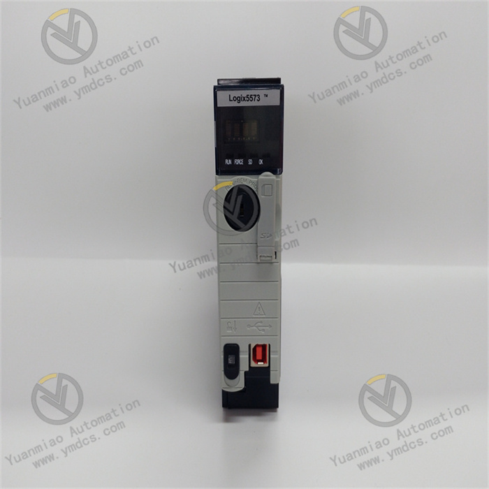
Technical Specifications for 1756-PBXT
| Manufacturer | Rockwell Automation |
| Brand | Allen-Bradley |
| Part Number/Catalog No. | 1756-PBXT |
| Series | ControlLogix |
| Module Type | DC Power Supply Module with Extended Temperature |
| Input Voltage | 24 Volts DC |
| Voltage Range | 18-32 Volts DC |
| Listing | This specification list was created by Do-Supply-Inc. |
| Input Power | 81 Watts |
| Power Output | 52 Watts |
| Isolation Voltage | 250 Volts Continuous |
| Weight | 3.2 pounds (1.45 kilograms) |
| Dimensions | 6.9 x 5.7 x 5.4 inches |
| Operating Temperature | 32-140 Fahrenheit (0-60 Celsius) |
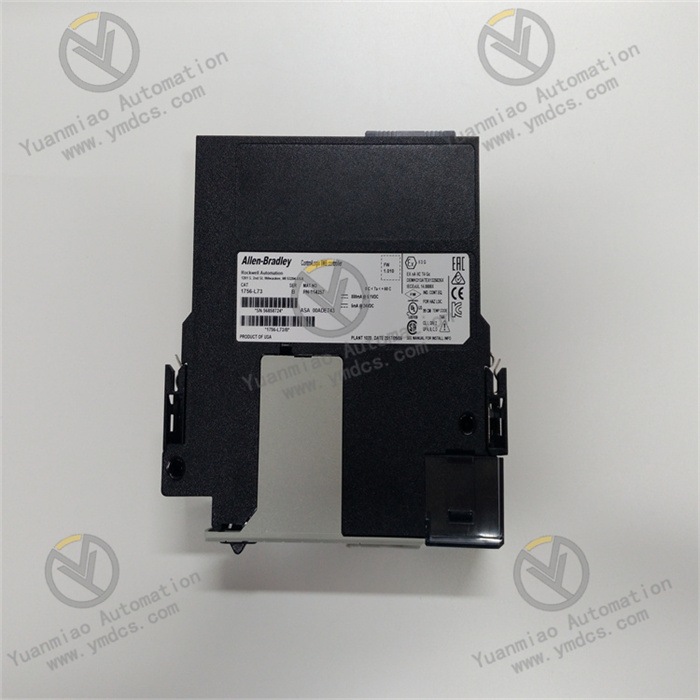
Working Principle:
- Input Circuit
Power access: The 1756 - PBXT power module is usually connected to an external AC power supply, generally 120V or 230V AC. It is connected to the external power line through the power input terminal to provide power input for the module.
Filtering and rectification: The connected AC power first passes through a filtering circuit to filter out high-frequency noise and interference signals in the power supply to ensure the purity of the input power. Then, the AC power is converted into DC power through a rectifier circuit. Generally, a diode bridge rectifier circuit or other methods are used to convert the sinusoidal AC power into pulsating DC power. - Power Conversion Circuit
DC-DC conversion: The DC power after rectification is not the stable DC voltage finally output by the module. It needs to be converted into a specific DC voltage suitable for the control system through the power conversion circuit. The 1756 - PBXT power module generally adopts switching power supply technology. By controlling the conduction and cut-off of the power switch tube, the input DC voltage is converted into high-frequency pulse voltage.
Transformer transformation: The high-frequency pulse voltage is transformed by a high-frequency transformer to output different voltage levels according to the design of the module, such as 24V DC, to meet the power supply requirements of various modules and devices in the ControlLogix system. At the same time, the transformer also plays a role in electrical isolation, isolating the input power from the output power to improve the safety and stability of the system. - Voltage Regulation and Protection Circuit
Voltage regulation control: To ensure the stability of the output voltage, a voltage regulation control circuit is built into the power module. It samples the output DC voltage and compares it with the internally set reference voltage. According to the comparison result, it adjusts the conduction time of the power switch tube to achieve stable control of the output voltage. Regardless of fluctuations in the input voltage or changes in the load, it can ensure that the output voltage remains stable within the specified range.
Overcurrent protection: When the output current exceeds the rated current of the module, the overcurrent protection circuit can detect it in a timely manner and take measures to limit the current. Generally, it reduces the conduction time of the power switch tube or turns off the switch tube to prevent the power module from being damaged due to overcurrent and also protects other devices connected to the power module.
Overvoltage protection: If the output voltage exceeds the set safe value, the overvoltage protection circuit will act quickly. Usually, it cuts off the power output or takes other voltage limiting measures to prevent the load devices from being damaged by excessive voltage.
Overheat protection: A temperature sensor is provided inside the power module to monitor the working temperature of the module. When the temperature reaches a certain threshold, the overheat protection circuit will be activated, reducing the output power of the module or stopping its operation until the temperature drops to a safe range to avoid permanent damage to the module due to overheating. - Output Circuit
The stable DC voltage after voltage regulation and protection processing is output to the backplane bus of the ControlLogix control system through the output terminal to provide a stable power supply for various modules in the system, such as the processor module and the I/O module, ensuring the normal and reliable operation of the entire control system. At the same time, the output circuit may also include some filtering and anti-interference measures to further improve the quality of the output power and reduce electromagnetic interference to other modules.
Common Faults and Solutions
- Power Indicator Light Not On
Fault cause: It may be caused by reasons such as the input power not being connected, the fuse being blown, or an internal fault of the power module.
Solution: First, check whether the input power is normal, ensure that the power cord is firmly connected, and measure whether the input voltage is within the specified range. If the input power is normal, check whether the fuse is blown. If it is blown, replace it with a fuse of the same specification. If the above checks are normal, it may be an internal fault of the power module, and the module needs to be repaired or replaced. - Abnormal Output Voltage
Fault cause: It may be caused by reasons such as load overload, power module failure, or a short circuit in the output line.
Solution: Check whether the load exceeds the rated load capacity of the power module. If there is an overload, reduce the load or replace the power module with a larger capacity. Check whether there is a short circuit in the output line. If there is a short circuit, repair the short-circuit point. If the load and the line are normal, try to reset the power module. If the output voltage is still abnormal after resetting, it may be a fault in the voltage regulation circuit inside the power module, and professional maintenance or replacement is required. - Module Overheating
Fault cause: It may be caused by reasons such as poor heat dissipation, too high ambient temperature, or aging of internal components of the module.
Solution: Check whether the installation location of the module has good ventilation and whether there is enough heat dissipation space around. Clean the surface of the module and the surrounding area of dust and debris to improve the heat dissipation conditions. At the same time, check whether the ambient temperature exceeds the allowable working temperature range of the module. If necessary, take measures to reduce the ambient temperature. If the heat dissipation and the ambient temperature are normal, it may be that the internal components of the module are aged or there is a fault, and professional personnel need to be contacted for maintenance. - Communication Fault
Fault cause: It may be caused by reasons such as a damaged communication interface, incorrect communication protocol settings, or electromagnetic interference.
Solution: Check whether the communication interface is loose or damaged. If there are problems, re-plug or replace the communication interface. Confirm whether the communication protocol settings match the PLC system. If there are errors, re-set the communication parameters. In addition, check whether there are strong electromagnetic interference sources around and take measures such as shielding and filtering to reduce electromagnetic interference. If the above methods cannot solve the problem, it may be a fault in the communication circuit inside the power module, and professional maintenance is required.
![]()


