Description
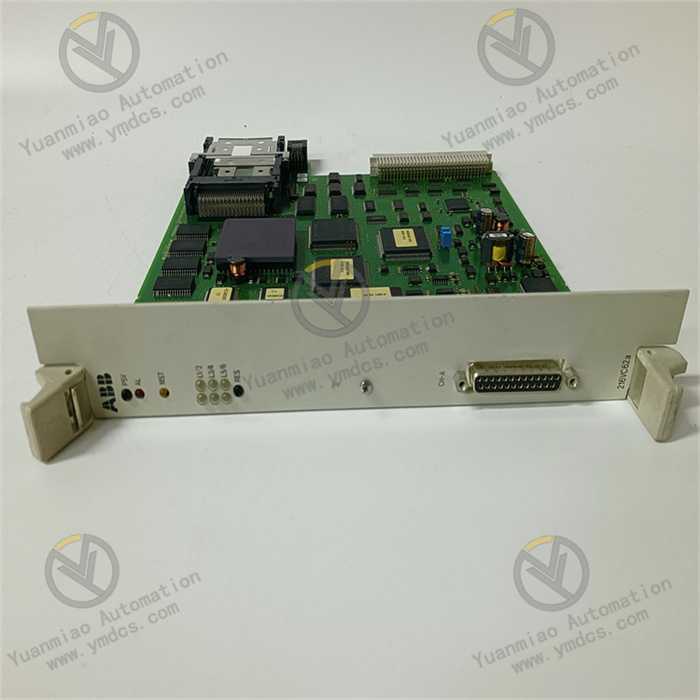
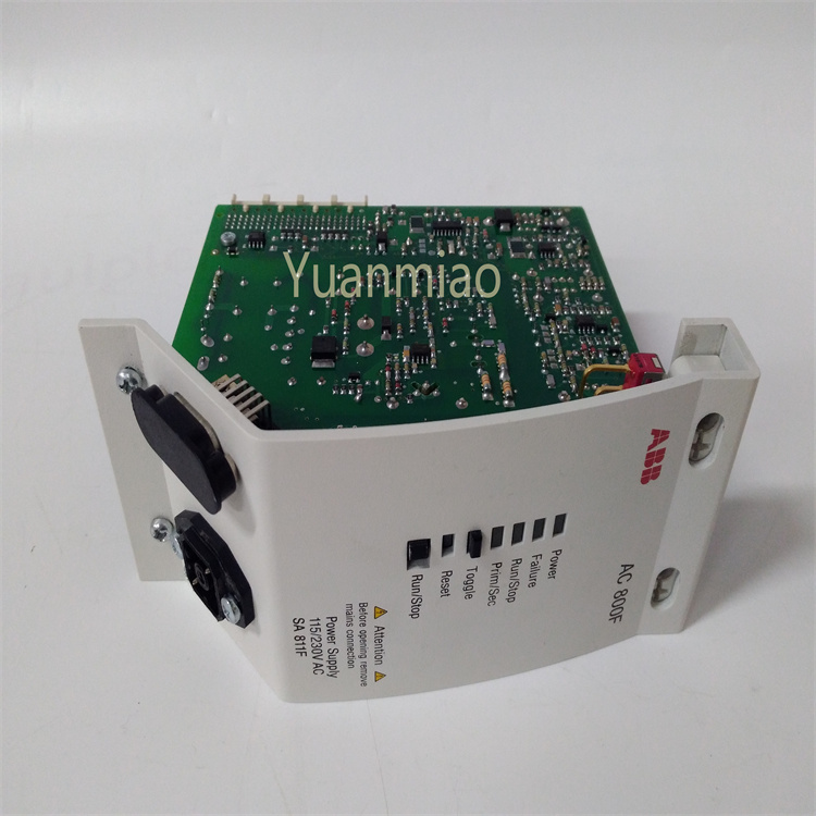
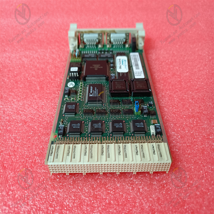
ABB CI532V01 3BSE003826R1
ABB CI532V01 3BSE003826R1 is a communication interface card.
Functions and Applications
As an RCOM interface card, it is used to establish communication connections between devices, playing a role in data transmission and communication protocol conversion in automation control systems. It helps different devices or systems carry out effective information interaction to achieve coordinated operation of the overall system.
Technical Parameters
- Communication Channels: Equipped with 2 channels, enabling simultaneous connection of multiple devices or data transmission on different lines.
- Operating Voltage: Typically 24V DC.
Product Features
- High Reliability: Designed and manufactured in accordance with ABB's high-quality standards, it can operate stably in industrial environments, adapt to environmental changes within a certain range of temperature and humidity, and has anti-interference capabilities to ensure communication stability and data accuracy.
- Compatibility: Compatible with various ABB automation devices and systems, facilitating user integration and expansion in existing ABB control systems, and reducing compatibility issues and system integration difficulties.
Troubleshooting Methods for Communication Failures of ABB CI532V01 3BSE003826R1
1. Basic Module Information
CI532V01 is a Modbus RTU communication module in ABB's industrial automation system, supporting RS485 communication, and is commonly used to connect devices such as sensors and actuators. Its core functions include:
- Communication Protocol: Modbus RTU (RS485 interface, 2 channels).
- Operating Voltage: 24VDC (±10%).
- Typical Applications: Data transmission and device integration in industrial automation networks.
2. Communication Fault Troubleshooting Steps
(1) Preliminary Hardware Inspection
- Power Supply and Indicator Status
- Power Light (PWR)
- Normal: Constant on (24VDC power supply normal).
- Abnormal:
- Off: Check if the power adapter and terminal connections are loose, and measure the voltage with a multimeter to ensure it is 24VDC.
- Flashing: Unstable voltage, possibly due to insufficient power capacity or poor circuit contact.
- Communication Light (COM)
- Normal: Periodic flashing (indicating normal data transmission and reception).
- Abnormal:
- Off: No communication signal, possibly due to disconnected cables, parameter errors, or module damage.
- Constant on: Communication anomalies (e.g., protocol mismatch, data frame errors).
- Fault Light (ERROR)
- On/Flashing: Hardware failure, communication parameter errors, or external interference.
- Physical Connection Check
- Power Cables: Ensure terminals are free from oxidation and looseness, and cables are undamaged.
- Communication Cables:
- Use shielded twisted-pair cables and check if RS485 A/B wires are reversed, loosely connected, or damaged.
- Terminal Resistor: For multi-node networks, a 120Ω resistor must be connected at the end (the module may have a built-in resistor enabled via a jumper cap).
- Cable Length: Modbus RTU is recommended to be no more than 1,200 meters; a repeater is required for excessively long cables.
- Grounding: The shield layer should be grounded at a single point (connected to the metal shell of the control cabinet) to avoid electromagnetic interference.
(2) Communication Parameter Configuration Verification
Check parameters via ABB programming software (e.g., Control Builder M) or Modbus debugging tools (e.g., Modbus Poll):
Check parameters via ABB programming software (e.g., Control Builder M) or Modbus debugging tools (e.g., Modbus Poll):
- Slave Address: Must be unique (range: 1-247) and consistent with the master station (e.g., PLC).
- Baud Rate: Must match the master station (e.g., 9600, 19200, etc.).
- Data Format:
- Data bits: 8 bits (default).
- Stop bits: 1 or 2 bits (must match the master station).
- Parity: None, Odd, or Even.
- Protocol Type: Confirm the use of Modbus RTU (not TCP or other protocols).
(3) Scenario-Based Fault Troubleshooting
- Scenario 1: No Power Supply or Abnormal Power Supply
- Troubleshooting Steps:
- Measure the voltage at the power terminal. If it is 0V, check the upstream power switch, fuse, or power distribution module.
- If the voltage is low (e.g., <21.6V), check if the power cable gauge is sufficient, terminal contact is good, or the power load is too high.
- Solutions:
- Replace power cables, tighten terminals, or upgrade the power capacity (ensure the load current ≤ module rated value).
- If the module overheats, internal short-circuit may occur, requiring module replacement.
- Scenario 2: Abnormal Communication Indicator (COM Light Not Flashing or Constant On)
- Troubleshooting Steps:
- Confirm that the master station (e.g., PLC) is working properly and the communication port is free from faults (try replacing the master station port for testing).
- Use a serial debugging tool (e.g., Modbus Poll) to directly connect to the module and send test commands (e.g., read register 0x0001):
- No response: Slave address error, baud rate/parity mismatch, or reversed cable connections.
- Erroneous response: Data frame format errors (e.g., incorrect stop bits) or module failure.
- Solutions:
- Reconfigure parameters to ensure full consistency with the master station.
- Swap RS485 A/B wires or replace the cable for testing.
- If single-node testing is normal, check for address conflicts or unused terminal resistors in multi-node scenarios.
- Scenario 3: Intermittent Communication Interruptions or Data Errors
- Troubleshooting Steps:
- Check for strong electromagnetic interference sources (e.g., frequency converters, motors) and temporarily remove them for testing.
- Test the loop resistance (ensure no open circuits) and insulation resistance (ensure no ground short circuits) of the cables.
- Test in single-node mode (only the module and master station connected) to eliminate multi-device networking conflicts.
- Solutions:
- Add shielding to cables or keep them away from interference sources, ensuring good grounding.
- Enable module line redundancy (if supported) or replace with higher-quality cables (e.g., twisted-pair shielded cables).
- In multi-node networking, confirm that the number of nodes ≤ the module's maximum support (typically 32) and addresses are unique.
- Scenario 4: Software or Firmware Issues
- Troubleshooting Steps:
- Check the module's firmware version via programming software and compare it with the latest version on ABB's official website.
- Attempt to restore factory settings (backup configurations first) and redownload parameters.
- Solutions:
- Upgrade the firmware to the officially recommended version (note that a power cycle is required to take effect).
- If factory restoration is ineffective, the module's storage chip may be faulty, requiring return for repair or replacement.
(4) Replacement Testing and System-Level Debugging
- Replacement Testing:
- Install the faulty module into a normally operating same-model system and observe performance:
- If normal, the original system may have power supply, grounding, or interference issues.
- If still faulty, the module hardware is damaged (e.g., communication chip, circuit board), requiring replacement.
- Replace the original module with a spare module to verify if the defect lies with the module itself.
- System-Level Coordination Testing:
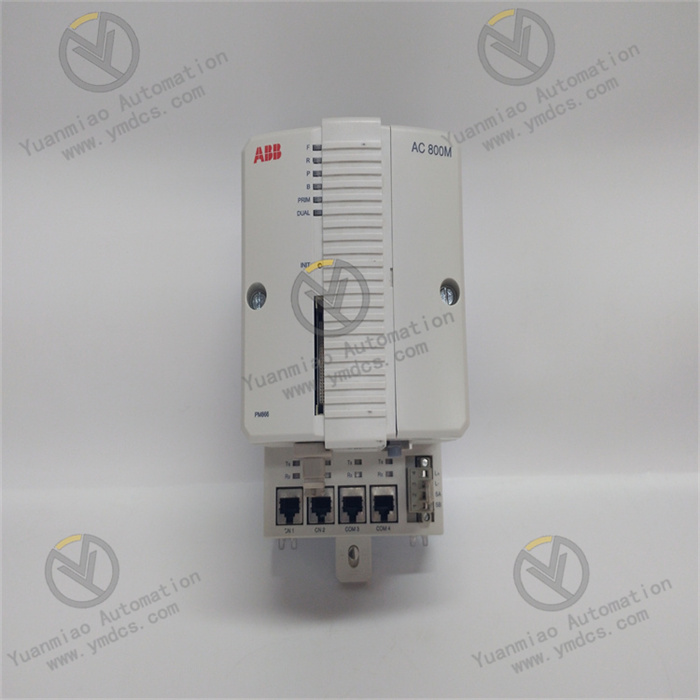
- Integrate with controllers (e.g., ABB AC 800M) and HMIs to simulate actual working conditions for data transmission/reception testing. Check for program logic issues such as:
- Excessively short timeout settings (needs to match the communication rate).
- Register address conflicts (e.g., master station reads an address different from the slave device's actual address).