Description
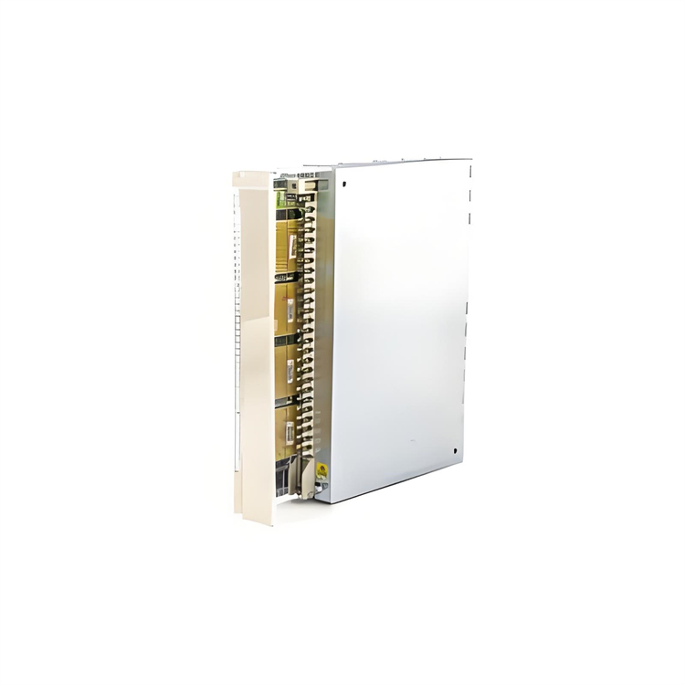
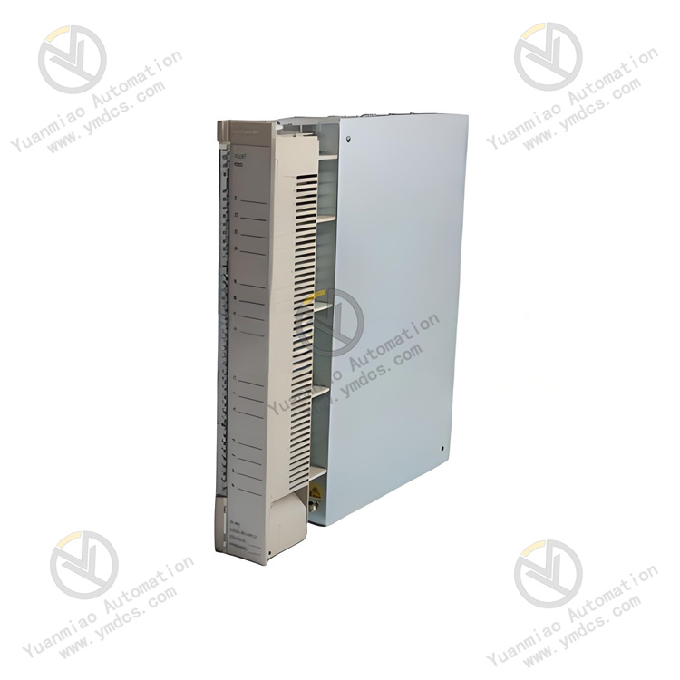
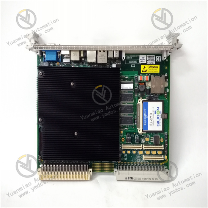
Abaco Systems VMIPCI-5565-110000
I. Overview
The Abaco Systems VMIPCI-5565-110000 is a high-performance PCI-interface industrial motion control card, specifically designed for high-precision multi-axis motion control scenarios. Serving as a core control bridge between upper computers, servo drives, and stepper motor drives, it enables precise planning, real-time control, and status monitoring of multi-axis motion. This product is widely used in fields with strict requirements for motion control accuracy and response speed, such as CNC machine tools, robotic automation, electronic manufacturing equipment (e.g., semiconductor packaging, PCB drilling machines), laser processing equipment, and automated production lines.
Adopting a 32-bit high-performance embedded processor and a dedicated motion control chip architecture, the product features multi-axis synchronous control, a rich set of motion modes, high-speed pulse output, and precise position feedback acquisition capabilities. It is compatible with standard PCI bus specifications, allowing seamless integration into industrial computers. When paired with Abaco's dedicated motion control software development kit (SDK), it supports users in quickly implementing custom motion control logic, providing a highly reliable and scalable solution for complex motion control scenarios.
II. Technical Parameters
| Parameter Category | Specific Specifications | Description |
|---|---|---|
| Axis Control Capability | Number of controlled axes: 8 axes (independent/synchronous control); Motion modes: Point-to-Point (PT) motion, linear interpolation, circular interpolation, continuous path control, electronic cam, electronic gearing; Interpolation accuracy: ±0.001 pulse | Multi-axis synchronous control meets the needs of complex trajectory motion; high-precision interpolation ensures processing and positioning accuracy |
| Pulse Output | Output type: Differential pulses (A/B-phase quadrature pulses, pulse + direction); Output frequency: Max. 2MHz per axis, max. 1MHz for 8-axis synchronous output; Pulse resolution: 1 pulse/step; Output driving capability: 5V/24V compatible, max. load current 100mA/channel | High-frequency pulse output adapts to high-speed motor drives; differential signal output enhances anti-interference capability; compatible with voltage specifications of mainstream drives |
| Position Feedback Input | Input type: Incremental encoder (A/B-phase quadrature signal), absolute encoder (SSI protocol, optional); Input frequency: Max. 5MHz; Input signal: 5V differential/single-ended, compatible with RS422 standard; Feedback accuracy: Dependent on encoder resolution (supports up to 16-bit encoders) | High-speed feedback input collects motor position information in real time to achieve closed-loop control; optional absolute encoder adapts to scenarios requiring power-off position memory |
| I/O Interfaces | Digital input: 16-channel optically isolated inputs, 24V DC, response time ≤1μs; Digital output: 16-channel optically isolated outputs, 24V DC, max. load current 500mA/channel; I/O isolation voltage: 2500V AC (between input/output and system ground) | Rich isolated I/O interfaces adapt to auxiliary control needs such as limiting, emergency stop, and clamping; strong isolation ensures signal stability |
| Bus & Communication | Bus type: PCI 2.3 specification, 32-bit/33MHz; Communication interfaces: On-board JTAG debugging interface, RS232 configuration interface; Data transmission rate: Max. 132MB/s via PCI bus | Standard PCI bus adapts to mainstream industrial computers; high-speed data transmission ensures real-time interaction of control commands and feedback data |
| Operating Environment | Operating temperature: 0℃-60℃; Storage temperature: -40℃-85℃; Relative humidity: 5%-95% (no condensation); EMC resistance: Compliant with EN 61000-4-2/3/4 standards; Vibration: 5-2000Hz, 1.5g (peak-to-peak) | Adapts to harsh industrial on-site environments; vibration and EMC resistance ensure stable equipment operation |
| Physical & Power Parameters | Dimensions: 167.6mm×106.7mm (standard half-length PCI card); Power supply method: Powered via PCI bus (+5V DC); Power consumption: ≤10W (full load); Weight: Approx. 150g | Standard half-length PCI card design adapts to slots of most industrial computers; bus-powered design simplifies installation and wiring |
III. Functional Features
- Multi-Axis High-Precision Synchronous Control: Supports 8-axis independent or synchronous motion control, with linear interpolation (up to 8 axes), circular interpolation (2 axes), and continuous path control functions. The interpolation accuracy reaches ±0.001 pulses, enabling precise implementation of complex trajectory motion. Built-in electronic cam and electronic gearing functions: the electronic cam supports customization of 1024-point cam curves, and the electronic gear ratio can be adjusted in real time (range: 1:1000 to 1000:1), adapting to scenarios such as assembly line synchronous transmission and cam profiling processing.
- High-Speed Pulse Output & Feedback Closed-Loop: The maximum pulse output frequency per axis is up to 2MHz, and it can still reach 1MHz when 8 axes output synchronously, enabling driving of high-speed servo or stepper motors for rapid positioning. Equipped with 8 high-speed position feedback input channels, it supports incremental encoders (max. 5MHz input) and optional absolute encoders. By collecting motor position information in real time, it forms closed-loop position control, effectively suppressing positioning errors caused by load changes. The positioning accuracy depends on the encoder resolution, supporting up to 16-bit absolute encoders.
- Rich Motion Control Functions: Supports multiple motion modes, including point-to-point motion (configurable acceleration/deceleration curves, target position, speed), Jog motion (manual jogging with adjustable speed), profile motion (operation along preset trajectories), and trigger motion (motion activation via digital input or software commands). It features motion interruption and emergency stop processing functions, with an emergency stop signal response time ≤1ms, which can quickly cut off motion output to ensure equipment and personnel safety.
- Strong Anti-Interference & High-Reliability Design: Digital I/O and position feedback inputs adopt optical isolation design with an isolation voltage of 2500V AC, effectively preventing the impact of strong electrical interference in industrial sites on control signals. Pulse output uses differential signals, and long-distance transmission (max. 50 meters) can be achieved with shielded cables, reducing signal attenuation and crosstalk. Industrial-grade components and enhanced PCB layout are used, with overvoltage and overcurrent protection functions, and the Mean Time Between Failures (MTBF) is ≥150,000 hours.
- Convenient Development & Debugging Support: Provides a motion control software development kit (SDK) for Windows and Linux systems, including function libraries and sample codes for multiple programming languages such as C/C++ and C# , supporting users to quickly develop custom motion control programs. The on-board JTAG debugging interface and RS232 configuration interface allow real-time monitoring of axis motion status, pulse output frequency, feedback position, and other parameters through dedicated debugging software, supporting online modification of motion parameters and fault diagnosis.
- Flexible I/O Expansion & Integration: Equipped with 16-channel isolated digital inputs and 16-channel isolated digital outputs, it can directly connect to peripheral devices such as limit switches, emergency stop buttons, solenoid valves, and indicator lights without additional I/O modules. It supports data interaction with devices such as PLCs and HMIs through industrial computers, and motion control programs can be seamlessly integrated with upper computer monitoring systems to realize functions such as real-time motion status display, parameter setting, and fault alarm.
IV. Working Principle
The core working principle of the Abaco Systems VMIPCI-5565-110000 motion control card is to achieve precise motion control of multi-axis motors through a closed-loop control process of "command reception → trajectory planning → pulse output → feedback acquisition → closed-loop adjustment", as detailed below:
- Initialization & Command Reception Stage: After the control card is inserted into the PCI slot of the industrial computer, hardware initialization is completed via the PCI bus. The upper computer sends initialization parameters (such as axis number assignment, pulse output mode, feedback type, and acceleration/deceleration curve parameters) to the control card through the motion control SDK. During operation, the upper computer sends motion commands (such as target position and speed for point-to-point motion, and trajectory point coordinates for interpolation motion), which are transmitted to the embedded processor of the control card via the PCI bus.
- Trajectory Planning & Pulse Generation Stage: After receiving the motion commands, the embedded processor calls the corresponding motion control algorithms for trajectory planning based on the command type: In point-to-point motion mode, it calculates the motor speed change curve according to the acceleration/deceleration curve (e.g., S-curve, trapezoidal curve) and determines the number of pulse outputs in each control cycle; In interpolation motion mode, it decomposes complex trajectories into multiple tiny line segments through interpolation algorithms and calculates the pulse allocation for each axis in each control cycle. The trajectory planning results are transmitted to the dedicated motion control chip, which generates high-precision pulse signals (A/B-phase or pulse + direction).
- Pulse Output & Motor Driving Stage: The pulse signals generated by the motion control chip are processed by a differential amplifier circuit and then transmitted to the servo or stepper motor drive through the pulse output channel. The drive drives the motor to operate according to the pulse frequency (corresponding to motor speed) and pulse number (corresponding to motor displacement). At the same time, the digital output channel of the control card can send auxiliary control signals such as enable and clamp to cooperate with motor motion to complete the entire control process.
- Position Feedback Acquisition & Closed-Loop Adjustment Stage: When the motor is running, the encoder (incremental or absolute) collects the motor rotor position information in real time and transmits the A/B-phase quadrature signal or SSI protocol signal to the feedback input channel of the control card. After the feedback signal is processed by isolation and shaping circuits, the motion control chip parses it into current position data and transmits it to the embedded processor. The processor compares the current position data with the target position data to calculate the position deviation. If the deviation exceeds the allowable range, it dynamically adjusts the pulse output frequency or number to achieve closed-loop position control, ensuring the motor runs accurately to the target position.
- I/O Interaction & Fault Handling Stage: The control card monitors the status of the digital input channels in real time, such as limit switch signals (triggered when the motor reaches the limit position) and emergency stop signals. When a limit or emergency stop signal is detected, the processor immediately sends a command to stop pulse output, cut off the motor enable, and report fault information to the upper computer via the PCI bus. The digital output channel sends corresponding control signals at specific nodes according to the motion process requirements (e.g., outputting a motor enable signal at the start of motion and a completion signal at the end of motion) to realize collaborative work with peripheral devices.
V. Common Faults & Solutions
| Fault Phenomenon | Possible Causes | Solutions |
|---|---|---|
| The upper computer fails to recognize the control card after insertion | 1. Poor contact or fault of the PCI slot; 2. Incorrect installation of the control card driver; 3. Fault of the industrial computer's PCI bus; 4. Hardware fault of the control card | 1. Power off, reinsert the control card to ensure it is fully inserted into the slot and fixed; 2. Uninstall the old driver and reinstall the latest driver for the corresponding operating system; 3. Insert the control card into another PCI slot for testing; if it still cannot be recognized, check the PCI bus of the computer motherboard; 4. Test with a spare control card, and contact Abaco after-sales service for repair if the fault is confirmed |
| The motor does not move, and there is no signal from the pulse output channel | 1. Motion commands not sent correctly (program logic error); 2. Motor enable signal not output; 3. Incorrect configuration of pulse output mode; 4. Fault of the pulse output channel; 5. Drive not powered on or faulty | 1. Monitor the command transmission status through debugging software to troubleshoot program logic errors; 2. Check the enable signal of the digital output channel and reconfigure the enable logic; 3. Verify the matching between the pulse output mode (A/B-phase/pulse + direction) and the drive, and reconfigure if necessary; 4. Use an oscilloscope to measure the pulse output channel; if there is no signal, contact after-sales service for repair; 5. Check the drive power supply, test the drive with a signal source, and replace the faulty drive |
| Excessive motor motion accuracy deviation | 1. Abnormal encoder feedback signal or uncalibrated encoder; 2. Unreasonable acceleration/deceleration curve parameters; 3. Pulse loss due to excessively high pulse output frequency; 4. Excessive backlash in the mechanical transmission mechanism; 5. Unoptimized closed-loop control parameters | 1. Check the encoder wiring, measure the feedback signal with an oscilloscope, and recalibrate the encoder; 2. Adjust the acceleration/deceleration time to avoid inertia deviation caused by sudden speed changes; 3. Reduce the pulse output frequency or optimize the control card clock frequency to reduce pulse loss; 4. Check mechanical transmission components (e.g., gears, lead screws) to eliminate backlash; 5. Optimize closed-loop proportional and integral parameters through debugging software |
| Motor jitter or abnormal noise during operation | 1. Too low pulse frequency or unsmooth speed curve; 2. Encoder signal interfered; 3. Improper drive parameter settings (e.g., gain); 4. Eccentric connection between motor and load; 5. Excessive power supply voltage fluctuation | 1. Increase the pulse output frequency and switch to S-curve acceleration mode; 2. Check the grounding of the encoder cable shield and add a signal isolator; 3. Re-adjust drive parameters (e.g., gain) to match motor characteristics; 4. Correct the coaxiality of the motor and load to reduce mechanical vibration; 5. Measure the power supply voltage of the control card and drive, and add a voltage stabilizer or power filter |
| No signal or abnormal response from digital I/O interfaces | 1. Incorrect I/O wiring or poor contact; 2. Incorrect I/O interface configuration (confused input/output direction); 3. Fault of the optical isolation circuit; 4. Fault of peripheral devices | 1. Check the I/O wiring against the manual, re-tighten terminals, and replace broken cables; 2. Verify the I/O interface configuration through debugging software and correct the input/output direction; 3. Measure the I/O channel voltage with a multimeter; if the isolation circuit is faulty, contact after-sales service for repair; 4. Replace peripheral devices (e.g., limit switches, solenoid valves) for testing to troubleshoot device faults |
| Inter-axis deviation during multi-axis synchronous motion | 1. Inconsistent acceleration/deceleration parameters of each axis; 2. Pulse loss in some axes; 3. Unoptimized synchronous control parameters; 4. Unbalanced mechanical load of each axis | 1. Standardize the acceleration/deceleration curve parameters of each axis to ensure consistent motion characteristics; 2. Reduce the pulse frequency during synchronous motion and check the cable shield grounding; 3. Optimize synchronous control parameters (e.g., electronic gear ratio, interpolation cycle) through debugging software; 4. Adjust the mechanical load distribution to ensure balanced load on each axis |