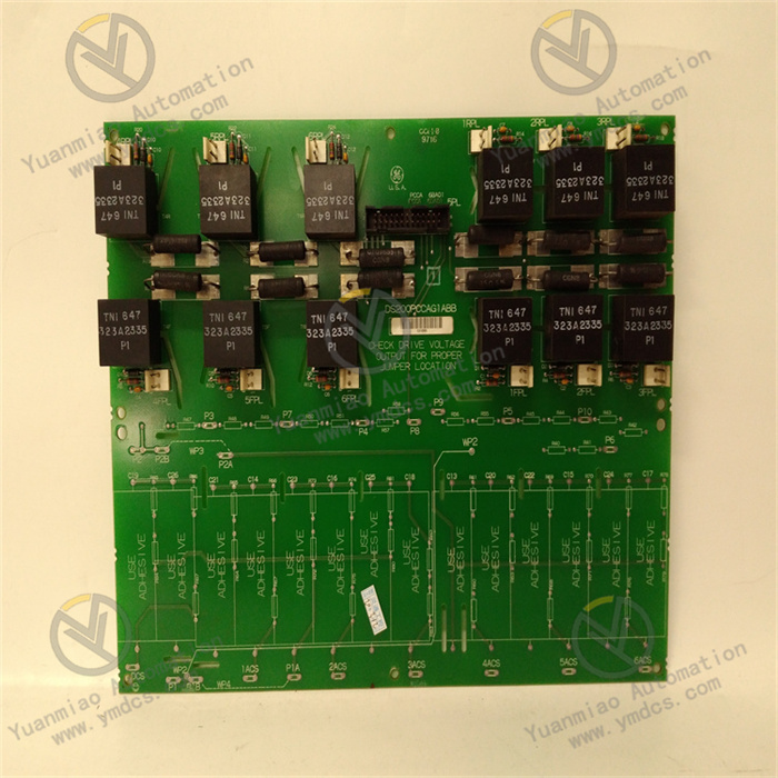
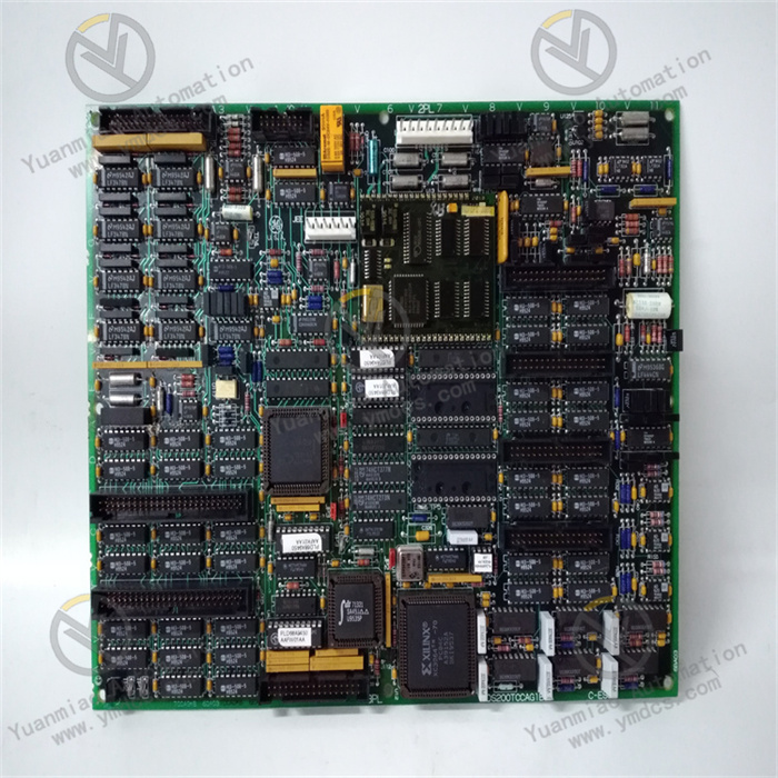
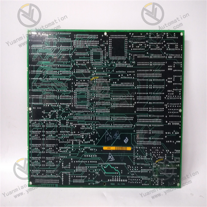
GE DS200NATOG1ABB | Contactor Pilot Board

GE DS200NATOG1ABB | Contactor Pilot Board

Brand: General Electric

Product ID: DS200NATOG1ABB

Condition: New / used

Terms of payment: Paypal、T/T 、Western Union

Category:

Description

GE DS200NATOG1ABB

I. Overview


GE DS200NATOG1ABB is a speed control module positioned as the "Core Unit for Precise Speed Regulation and Overspeed Safety Protection of Large-Scale Steam Turbines". It is mainly applied in steam turbine control systems in fields such as thermal power generation, nuclear power generation, and industrial drives. Undertaking key tasks including stable speed control, precise acceleration rate adjustment, and overspeed fault protection, it provides reliable hardware support for the full operating cycle of steam turbines, ranging from start-up and speed-up, grid connection with load, normal operation to emergency shutdown.


Deeply integrated into the Mark VI control system architecture, this module adopts a high-precision speed closed-loop control algorithm, an independent overspeed protection logic unit, and a multi-redundancy design. It can directly connect to executive mechanisms of steam turbines such as high-pressure control valves, medium-pressure control valves, and main steam valves. Without the need for additional adapter modules, it realizes full-link closed-loop control covering "speed signal acquisition - command calculation - regulation output - status feedback". Its core advantages lie in high speed measurement accuracy, fast overspeed response (millisecond-level), wide adjustable range of acceleration rate, and strong compatibility with steam turbine regulation systems. It is applicable to various scenarios, including 300MW-1000MW thermal power steam turbines, nuclear power conventional island steam turbines, and large-scale backpressure steam turbines for industrial drives. Capable of long-term stable operation in harsh conditions such as a wide temperature range (-20℃ to 65℃), strong electromagnetic interference, and high vibration, it meets the strict requirements of the steam turbine industry for speed control accuracy (±0.1% rated speed) and safety redundancy.


II. Technical Parameters


Parameter CategorySpecification ParametersDetailed Description
Control & Signal ParametersAdaptation SystemGE Speedtronic Mark VI control system; compatible with Mark VI main controllers such as IC697CPU771; supports collaboration with ToolboxST configuration software, HMI operation interface, and DEH (Digital Electric Hydraulic) regulation system.

I/O Configuration6 speed signal inputs (compatible with magnetoresistive/photoelectric/Hall-effect sensors), 8 digital inputs (e.g., control valve status, emergency shutdown signal), 6 analog outputs (e.g., control valve opening command), 4 fault alarm outputs, 3 overspeed protection command outputs; built-in dedicated PID regulation chip.

Signal Adaptation RangeSpeed input: 0-10kHz (magnetoresistive), 0-5Vpp (photoelectric), supporting 3-channel redundant input; Digital input: 24V DC dry/wet contacts; Analog output: 4-20mA; Overspeed protection output: 24V DC dry contacts.

Control Accuracy IndicatorsSpeed measurement accuracy: ±0.01% rated speed; Speed regulation accuracy: ±0.1% rated speed; Acceleration rate regulation accuracy: ±0.5r/min/s; Control valve opening control accuracy: ±0.1% full stroke; Overspeed judgment response time: ≤1ms; PID regulation response time: ≤3ms.
Interface & Isolation ParametersField Interface5 sets of 36-pin pluggable terminal blocks (speed input/control valve output/power supply/redundant signal/protection output); Rated terminal current: 1A (signal interface), 5A (power interface); Wiring specification: 0.5-4mm²; Supports shielded cables, each set of terminals is equipped with an independent grounding terminal.

System InterfaceMark VI dedicated VME bus communication; Communication rate: 16Mbps (synchronous transmission); Supports hot swapping; Address DIP switch (adjustable 0-15); Supports 1:1 module-level redundant backup.

Isolation PerformanceIsolation between speed input and control circuit: 2500V AC (1min); Isolation between analog channels: 1000V AC; Digital I/O isolation: 1000V AC; Power supply isolation: 2500V AC; Common mode rejection ratio ≥130dB, differential mode rejection ratio ≥100dB.
Power Supply & Power ConsumptionPower Supply SpecificationDual-channel redundant power supply (DC 5V±5%, DC 24V±10%); Maximum current for 5V: 4A, maximum current for 24V: 3A; Equipped with four-fold protection against overvoltage, overcurrent, reverse connection, and surge.

Power Consumption IndicatorsTypical power consumption: ≤35W (3-channel control valve drive + speed closed-loop control); Standby power consumption: ≤6W; Maximum power consumption: ≤45W (full load of all channels); Natural heat dissipation + high-density heat sink design.
Environmental & Physical ParametersEnvironmental AdaptabilityOperating temperature: -20℃ to 65℃; Storage temperature: -40℃ to 85℃; Relative humidity: 5%-95% (no condensation); Vibration resistance: 10-2000Hz/2g (three axes); Shock resistance: 25g (peak 11ms); Compliant with IEC 61000-4 EMC standards.

Physical SpecificationsDimensions: 380mm×180mm×100mm (L×W×H); Embedded installation in Mark VI VME rack; Weight: approximately 4.0kg; Die-cast aluminum alloy housing (with anti-static and anti-corrosion coating); Protection class: IP30 (body), IP65 (optional terminal box).
Reliability & ProtectionReliability IndicatorsMTBF (Mean Time Between Failures): ≥1,000,000 hours; Service life: ≥15 years; Long-term stability of speed measurement: ≤0.005% rated speed/year; Redundancy switching response time: ≤2ms.

Protection FunctionsThree-level overspeed protection (103% rated speed for alarm, 110% for shutdown, 115% for emergency shutdown); Redundant judgment of speed sensors; Detection of control valve jamming; Dual-channel power supply redundant switching; Emergency shutdown response: ≤1ms.


III. Functional Features


1. In-depth Collaboration with Mark VI System, Seamless Connection of Control Links

The module adopts the dedicated VME bus architecture of the Mark VI system and can be directly embedded in a standard VME rack. Mechanical fixation and electrical connection are achieved through high-density bus connectors, with installation and access taking only 30 minutes. After access, the ToolboxST software can automatically identify module information. Engineers can configure speed control parameters (such as PID coefficients, acceleration rate curves, and overspeed thresholds) through a graphical interface, supporting online debugging and offline simulation without the need to write underlying drivers. The data transmission adopts a synchronous communication mechanism: the speed data upload cycle is ≤1ms, and the command issuance delay is ≤0.5ms. When the grid frequency fluctuates by ±0.5Hz, the regulation closed loop can be completed within 5ms, ensuring the speed is stabilized within ±0.1% of the rated value.


2. Adaptation to Multiple Types of Sensors, Accurate and Stable Speed Measurement

It integrates 6 high-precision speed input channels, compatible with mainstream speed sensors such as magnetoresistive, photoelectric, and Hall-effect sensors. The input impedance of the magnetoresistive channel is ≤500Ω (adapting to 0-10kHz signals), and that of the photoelectric channel is ≥100kΩ (adapting to 0-5Vpp signals), with signal shaping and filtering functions. It supports 3-channel redundant sensor input and adopts "two-out-of-two" or "two-out-of-three" judgment logic. When a single sensor fails, it automatically switches to the redundant loop to ensure continuous measurement. The high sampling rate of 1kHz can accurately capture the dynamic speed changes during the start-up and speed-up phase, with a fluctuation identification accuracy of 0.1r/min within the sampling interval, providing reliable data support for acceleration rate control.


3. Precise Speed Control Under Full Operating Conditions, Flexible Adjustment of Acceleration Rate

Equipped with a variable-parameter PID regulation chip, it can automatically switch parameter sets according to steam turbine operating conditions: during the start-up and speed-up phase, "low-gain and slow-response" parameters are used, combined with a continuously adjustable acceleration rate curve of 0.5-10r/min/s to avoid excessive vibration; during the grid connection phase, "medium-gain and medium-response" parameters are adopted to quickly synchronize with the grid frequency; during the normal operation phase, "high-gain and fast-response" parameters are applied to suppress disturbances such as steam parameter fluctuations. It supports presetting of multiple acceleration rate curves: 2r/min/s can be set for cold start, and 5r/min/s for hot start, adapting to different start-up requirements. It is equipped with a feedforward compensation function, which can predict speed fluctuations based on steam parameters and output regulation commands 2ms in advance, effectively suppressing overshoot.


4. Three-level Overspeed Redundant Protection, Excellent Safety Performance

It adopts a dual-redundancy overspeed protection design combining an independent hardware unit and software logic, which is independent of the main control loop and powered by dual channels. The three-level protection logic is as follows: when the speed reaches 103% of the rated speed, an alarm is triggered and the acceleration rate/control valve is fine-tuned; when it reaches 110%, a shutdown command is output to close the high-pressure and medium-pressure control valves as well as the main steam valve (response time ≤1ms); when it reaches 115%, an emergency shutdown is triggered, linking with the emergency trip device to cut off steam supply. It has an online verification function for overspeed thresholds, and the response accuracy can be verified by inputting verification signals through ToolboxST. Redundant sensor cross-verification is adopted—protection is only triggered when at least 2 sensors detect overspeed, avoiding false shutdown caused by single-point faults.


5. Strong Anti-interference Design, Adaptation to Harsh Operating Conditions

The speed input and control loop adopt dual isolation (photoelectric + transformer) with an isolation voltage of 2500V AC, and the isolation between channels is 1000V AC, effectively blocking strong electromagnetic interference. With a common mode rejection ratio of ≥130dB, it can resist electromagnetic interference from equipment such as generators and frequency converters, as well as grid common mode interference. The die-cast aluminum alloy housing is coated with an anti-static and anti-corrosion layer, and the internal circuit board is treated with three-proof paint. Combined with anti-vibration terminals and shock-absorbing brackets, it can resist 2g vibration and high-temperature radiation. Compliant with IEC 61000-4 series EMC certifications, it operates stably in the harsh environment of steam turbine rooms.


6. Full-dimensional Intelligent Diagnosis, Improved Operation and Maintenance Efficiency

Equipped with 12 status indicator lights covering states such as power supply, communication, speed measurement, overspeed alarm, and sensor fault, it enables quick localization of fault scope. It supports module-level (power supply/communication fault), channel-level (sensor disconnection/output overcurrent), and function-level (PID logic/redundancy switching fault) diagnosis, with a fault response time of ≤2ms. Fault information (type, time, parameters) is uploaded to the main controller via the bus, triggering sound and light alarms and HMI pop-up prompts. 300 timestamped logs can be queried through ToolboxST. It supports online monitoring of data such as speed curves and control valve openings, and trend analysis can predict potential faults, reducing fault troubleshooting time by 90%.


IV. Common Faults and Solutions


Fault PhenomenonPossible CausesSolutionsPrecautions
Module fails to start, power indicator is offLoose power wiring, faulty power module, poor bus contact, incorrect address DIP switch setting1. Power off, check and fasten the 5V/24V wiring; 2. Measure the power output, replace with original module if abnormal; 3. Replug the module to ensure the bus is locked tightly; 4. Verify that the address DIP switch matches the system configuration.Disconnect the module power supply before measurement; Cut off the main power supply before wiring; Restart the system after modifying the address; Use GE original power modules.
Large speed display fluctuationLoose/aged sensor wiring, abnormal installation gap (0.5-1.5mm), faulty sensor, electromagnetic interference1. Fasten or replace wiring, confirm polarity; 2. Stop the unit and adjust the sensor gap to the standard range; 3. Detect signals with an oscilloscope, replace the sensor if waveform is distorted; 4. Check grounding (≤4Ω) and keep cables away from power lines.Adjust the sensor gap only when the unit is stopped; Wear insulating gloves during measurement; Replace sensors with the same model; Use independent grounding to avoid common grounding interference.
False action of overspeed protectionFalse alarm from faulty sensor, incorrect threshold setting, misjudgment due to interference, signal fluctuation caused by excessive vibration1. Compare data from 3 sensors and replace faulty ones; 2. Verify thresholds (103%/110%/115%); 3. Clean bus pins and strengthen grounding; 4. Verify protection logic and detect steam turbine vibration.Conduct a comprehensive inspection after false action; Threshold modification requires approval from technical supervisors; Isolate steam during logic verification; Vibration detection should be done by professionals.
Communication fault indicator is onOxidized/bent bus connector pins, address conflict, excessive bus load, faulty main controller interface1. Clean bus pins and check for bending; 2. Verify that the module address is unique; 3. Reduce the number of bus modules to keep load rate ≤70%; 4. Test the module by installing it in a normal slot.Use dedicated cleaning agent for cleaning; List all addresses when checking for conflicts; Check the load rate via system tools; Back up the program before restarting the controller.
Large deviation between control valve and commandLoose output wiring, faulty/uncalibrated positioner, uncalibrated channel, control valve jamming, improper PID parameters1. Fasten or replace wiring; 2. Calibrate or replace the control valve positioner; 3. Calibrate the analog output channel with a standard signal source; 4. Stop the unit to overhaul the control valve and optimize PID parameters.Calibration should be done when the unit is stopped; Regularly verify the signal source; Control valve overhaul requires professionals; Adjust PID parameters under low load.

contact us