Description
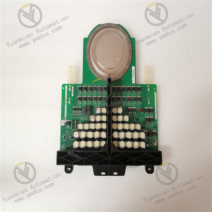
GE IS200EGDMH1ADF
I. Product Overview
The GE IS200EGDMH1ADF is a high-performance excitation gate pulse amplifier circuit board belonging to the Mark VI Speedtronic series. Specifically designed for the excitation control systems of steam turbines and gas turbines, it serves as a critical signal processing unit connecting the excitation controller and the actuator. Its core value lies in converting the weak logic signals output by the controller into strong power pulse signals to drive power electronic devices (such as thyristors) in the excitation system. Meanwhile, through its redundant design and multi-dimensional protection functions, it ensures the stable operation of the excitation circuit in turbine-generator units, making it suitable for controlling large rotating machinery in fields like electric power and petrochemicals.
This module features a compact structural design, supports rack-integrated installation in the Mark VI system, and has wide-temperature operation characteristics and authoritative safety certifications. It can achieve long-term reliable operation in harsh industrial environments and is a core power amplification component in GE's excitation control systems.
II. Technical Specifications
(I) Electrical Performance Parameters
Power Supply and Power Output
- Input Voltage: 24V DC (compatible with the standard power supply of the Mark VI system);
- Output Voltage: 120V AC (peak value of pulse output);
- Maximum Output Current: 5A (continuous operating current);
- Power Density: Suitable for the instantaneous power requirement of thyristor triggering in the excitation circuit.
Signal Interface Configuration
- Input Channels: 6 auxiliary contact input channels (independently powered by M1/M2 power supplies), capable of receiving switching signals from devices such as sensors and limit switches;
- Output Channels: 4 general-purpose relay output channels (in Form-C contact configuration) and 2 dedicated trip contact output channels, supporting switching between normally open/normally closed states;
- Signal Isolation: Electrical isolation is provided between the input and output circuits (referring to the isolation standard of ≥1500V DC for modules in the same series) to prevent signal crosstalk.
(II) Environmental and Physical Parameters
Environmental Adaptability
- Operating Temperature Range: -40°C to +85°C (wide-temperature design, adaptable to temperature fluctuations in the unit room);
- Storage Temperature Range: -40°C to +125°C (meeting the requirements of harsh transportation and storage conditions);
- Protective Treatment: The PCB board is coated with a conformal coating to resist moisture and dust erosion.
Physical Specifications
- Dimensions: 263mm × 138mm × 88mm (compact design, saving rack space);
- Weight: 2.35kg (compatible with the load-bearing standard of the rack);
- Installation Method: Backplane or panel installation in the Mark VI control chassis.
III. Core Functional Features
(I) Redundant Design and High Reliability
The module is specifically designed for redundant control system architectures and supports hot-backup configuration of main and standby modules. When a single component fails (e.g., abnormal output circuit, power failure), the system can automatically switch to the standby module to maintain excitation pulse output without interruption, significantly improving the operational fault tolerance of turbine-generator units. At the same time, high-quality industrial-grade components and an independent power isolation design are adopted to reduce the risk of faults at the hardware level.
(II) Flexible Signal Interaction Capability
Through 6 auxiliary contact input interfaces, it can collect real-time status signals in the excitation system (such as thyristor temperature and cooling system operating status) to provide accurate on-site data support for the controller. The 4 general-purpose relay output channels can be used to drive peripheral devices such as alarm indicator lights and intermediate relays, while the 2 dedicated trip contact output channels are specifically adapted to the emergency shutdown circuit. When a serious fault is detected, they quickly cut off the excitation power supply to ensure equipment safety.
(III) Compact Design and Easy Maintainability
Adopting a standardized size and modular structure, it can be directly integrated into the Mark VI system rack, reducing the occupied installation space. The module interfaces feature a plug-and-play design, and combined with clear terminal markings, they greatly shorten the installation and replacement time. Additionally, it supports communication with the Mark VI system's diagnostic bus, enabling remote reporting of the module's operating status (such as input signal loss and output overload), which reduces the difficulty of on-site operation and maintenance.
IV. Typical Application Scenarios
(I) Excitation Control of Steam Turbines in Thermal Power Plants
In the excitation system of 300MW-class steam turbines, the IS200EGDMH1ADF receives the excitation adjustment signal from the Mark VI controller, amplifies it into a 120V AC pulse signal, and accurately triggers the three-phase thyristor rectifier bridge to control the generator rotor excitation current. The 6 auxiliary input channels monitor the rectifier bridge temperature and cooling water pressure signals in real time. When the temperature exceeds the threshold, the trip output quickly cuts off the excitation circuit to prevent equipment burnout.
(II) Excitation System of Gas Turbines in Petrochemical Enterprises
In natural gas combined cycle power plants, this module serves as a core component of the gas turbine excitation cabinet. It cooperates with the excitation regulator to achieve stable voltage control of the generator after grid connection. Its wide-temperature operation characteristic enables it to adapt to high-temperature environments above 40°C in the equipment room, and the redundant design ensures that the unit can still maintain normal power generation when a single module fails, meeting the power demand for continuous production of petrochemical equipment.
(III) Excitation Drive of Generators in Large Hydropower Plants
For low-speed, large-inertia generators in hydropower plants, the module realizes step-by-step adjustment of the excitation system through 4 general-purpose relay output channels. Combined with the high reliability of Form-C contacts, it ensures smooth adjustment of the excitation current when the unit load fluctuates, reducing the impact of voltage fluctuations on the power grid.
V. Selection and Engineering Implementation Recommendations
(I) Selection Criteria
- System Compatibility: Only compatible with the GE Mark VI Speedtronic series excitation control systems. Non-series systems require conversion via a dedicated interface module, and cross-platform use is not recommended;
- Power Matching: Preferentially selected when the rated current of the thyristor in the excitation circuit is ≤5A; for currents exceeding 5A, a power expansion module must be used in conjunction;
- Redundancy Requirement: Redundant modules must be configured for critical units (such as main power grid supply units), while non-critical backup units can operate with a single module.
(II) Recommended Peripheral Configuration
- Power Supply Configuration: The standard 24V DC redundant power supply of the Mark VI system (e.g., IS200PWRCH1A) must be used to ensure that the input voltage fluctuation is ≤±5%;
- Wiring Specifications: Shielded twisted-pair cables (with a cross-sectional area of ≥0.5mm²) should be used for input signal cables; the distance between output pulse cables and power cables should be ≥500mm to avoid electromagnetic interference;
- Peripheral Adaptation: For trip output, the GE DS200 series emergency shutdown relays are preferentially matched; for general-purpose output, the Schneider RXM series intermediate relays are adapted.
(III) Installation and Commissioning Notes
- Installation Specifications: The module must be installed in a Mark VI standard control cabinet, with a distance of ≥150mm from the cooling fan to ensure ventilation and heat dissipation; the rack grounding resistance should be ≤4Ω to improve anti-interference capability;
- Parameter Configuration: Use the Mark VI System Toolbox software to configure the input signal filtering time (20ms is recommended) and output pulse width (adjusted according to the thyristor model);
- Commissioning and Verification:
- Redundancy Test: Disconnect the power supply of the main module, confirm that the switching time of the standby module is ≤100ms, and that the output signal is not interrupted;
- Fault Test: Simulate an input signal short circuit, check whether the module triggers overcurrent protection, and whether the output is locked in a safe state.


