Description
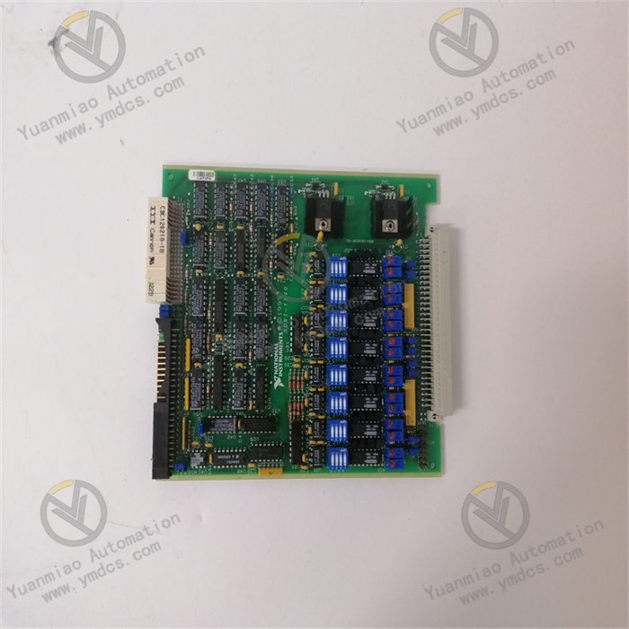
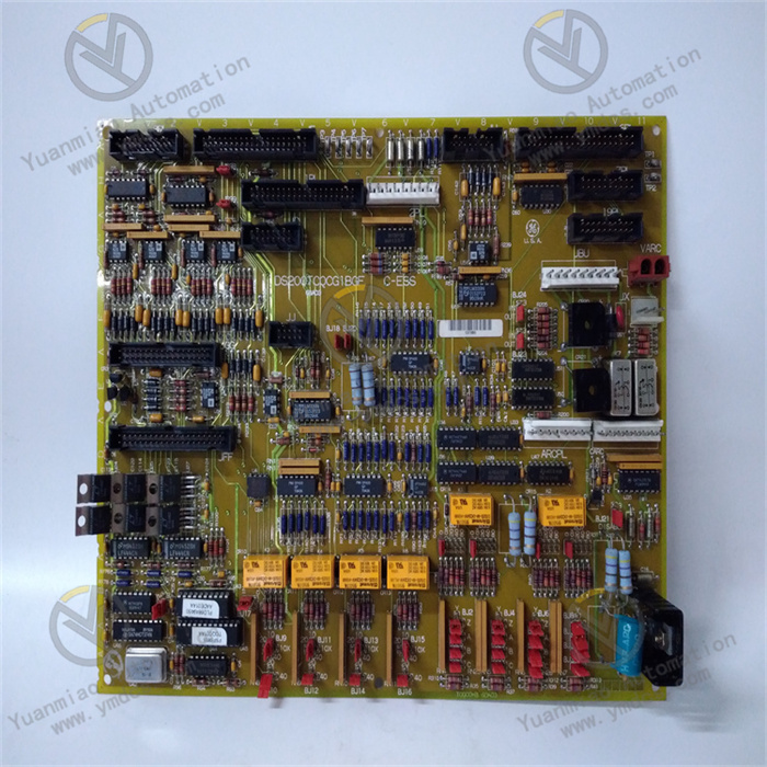
GE IS200EXHSG3AEC
I. Overview
GE IS200EXHSG3AEC is a signal processing gateway module for excitation systems. Its core value lies in providing an interactive solution featuring "multi-type signal conversion, high-speed synchronous transmission, and redundant communication guarantee" for the excitation system and Mark VIe main control system of turbine-generator units. Serving as the "signal translation and transmission hub" between the two, it enables the collection and conversion of key parameters such as excitation current, excitation voltage, and rotor temperature, as well as the issuance of excitation control commands from the main control system. It is suitable for excitation control scenarios of 300MW-1000MW thermal power units and gas turbines in combined cycle power plants, and is a key component ensuring the stable operation of the excitation system of turbine-generator units and the accurate regulation of grid voltage.
This module adopts a reinforced electromagnetic isolation design and a redundant communication architecture. It supports seamless integration with mainstream excitation systems such as GE EX2100 and ABB UNITROL, and combines signal processing accuracy with operational reliability. It serves as a core bridge connecting the excitation subsystem and the main control system in the Mark VIe system.
II. Technical Parameters
(I) Signal Processing and Conversion Parameters
1. Signal Input and Output Configuration
- Analog Input (Excitation System Parameter Collection): 8 channels of high-precision analog input (16-bit AD, input range of ±10V DC/4-20mA) for collecting:
- Excitation system parameters: Excitation current (0-5000A, converted to 4-20mA via current transformer), excitation voltage (0-1000V DC, converted to ±10V via voltage transmitter);
- Generator parameters: Rotor temperature (RTD signal, conditioned to 4-20mA), stator current (0-1000A, 4-20mA);Input accuracy is ±0.05% FS, meeting the high-precision parameter monitoring requirements of the excitation system.
- Analog Output (Main Control Command Issuance): 6 channels of analog output (16-bit DA, output range of ±10V DC/4-20mA) for sending to the excitation system:
- Excitation current setpoint (4-20mA, corresponding to 0-5000A), excitation voltage regulation command (±10V, compatible with excitation regulators);
- Emergency shutdown signal for the excitation system (4-20mA, triggered by low level);Output accuracy is ±0.1% FS, ensuring no deviation of control commands.
- Digital I/O (Status and Control): 12 channels of digital input (24V DC, for collecting excitation system fault signals and circuit breaker status), 8 channels of digital output (24V DC, for driving excitation system start-stop relays and fault alarm lights), with a response time of ≤1ms.
2. Signal Conversion and Synchronization
- Signal Conditioning: Built-in signal amplification and filtering circuits, supporting 50Hz/60Hz power frequency filtering for excitation current/voltage signals (filtering depth ≥40dB) to eliminate grid frequency interference;
- Synchronization Accuracy: The signal synchronization error with the Mark VIe main control system is ≤10μs (based on GE's dedicated synchronous clock protocol), ensuring the time consistency of excitation parameter collection and control command issuance;
- Range Adaptation: Supports software configuration of input/output signal ranges (e.g., mapping excitation current 0-3000A to 4-20mA without hardware jumpers), adapting to turbine-generator units of different capacities.
(II) Communication and Redundancy Parameters
1. Communication Interfaces and Protocols
- Internal Communication (with Mark VIe Main Control): Dual optical fiber interfaces (speed of 100Mbps, supporting GE SRTP protocol) for redundant communication with Mark VIe controllers (e.g., IS200TBSCH1A), with a communication delay of ≤50μs;
- External Communication (with Excitation System): 1 EtherNet/IP port (10/100Mbps, compatible with standard excitation system protocols), 1 RS-485 port (supporting Modbus RTU protocol for connecting to the local HMI of the excitation system);
- Synchronization Interface: 1 IRIG-B code input interface (time synchronization accuracy of ±1ms) to ensure synchronization with the grid dispatching clock, meeting the timestamp requirements for excitation regulation.
2. Redundancy Configuration
- Communication Redundancy: Dual optical fiber interfaces + EtherNet/IP dual-link redundancy. When the main communication link (e.g., Optical Fiber A) fails, the standby link (Optical Fiber B/EtherNet/IP) switches within ≤100μs without signal interruption;
- Power Redundancy: Supports dual-channel 24V DC redundant power supply (input voltage range of 18V-30V DC). The power consumption of a single module is ≤8W (under full-load signal processing), and automatic switching occurs in case of power failure without power supply interruption;
- Signal Redundancy: Key analog inputs (e.g., excitation current) support dual-channel collection and comparison. When the deviation between the two channels exceeds 5%, a fault alarm is triggered to avoid misjudgment caused by a single sensor failure.
(III) Electrical and Environmental Parameters (Suitable for Excitation Room Scenarios)
1. Isolation and Anti-Interference
- Isolation Performance:
- Signal Isolation: There is 2500V AC isolation (withstand voltage for 1 minute) between analog I/O and communication interfaces, and 1500V AC isolation between digital I/O and internal circuits. It has a common-mode interference voltage resistance of ±300V DC, resisting strong electromagnetic interference from the excitation system (e.g., magnetic fields generated by excitation transformers);
- Power Isolation: There is 2000V AC isolation between the input power supply and internal circuits, with power ripple suppression of ≤50mV (peak-to-peak);
- Electromagnetic Compatibility: Passes IEC 61000-4 series tests, withstanding ±15kV air discharge (ESD), ±4kV electrical fast transients (EFT), and 30V/m radio frequency interference (RFI), far exceeding the anti-interference level of ordinary I/O modules.
2. Environmental Adaptability
- Operating Environment: Temperature range of -10℃ to 65℃ (operation without derating, suitable for the high-temperature environment of excitation rooms); storage temperature range of -40℃ to 85℃; relative humidity of 5%-95% RH (no condensation, supporting short-term 98% RH humid environments);
- Protection Design: The module itself has an IP20 protection rating (to be installed in a Mark VIe standard control cabinet). The PCB board adopts a reinforced conformal coating (oil-proof and dust-proof, adapting to the oily environment of excitation rooms);
- Anti-Vibration Performance: Complies with IEC 60068-2-6 standard, with a vibration frequency of 10Hz-2000Hz and an acceleration of ≤20m/s², adapting to the vibration environment during turbine operation. The Mean Time Between Failures (MTBF) of the module is ≥150,000 hours.
(IV) System Compatibility and Diagnostic Parameters
1. System Adaptability
- Software Support: Compatible with GE Mark VIe ControlST V10.0 and above versions, supporting graphical configuration of signal ranges, communication parameters, and redundancy strategies, and providing dedicated diagnostic function blocks for the excitation system (e.g., excitation current deviation alarm, communication interruption protection);
- Device Compatibility: Directly compatible with GE EX2100 excitation system, ABB UNITROL 6800 excitation system, and Siemens S7-400 excitation control cabinet, without the need for dedicated drivers;
- Installation Method: Supports installation in Mark VIe standard I/O racks (directly inserted into rack slots), with dimensions consistent with IS200 series I/O modules (120mm×150mm×30mm), requiring no additional space.
2. Diagnosis and Maintenance
- Local Diagnosis: The module panel is equipped with 16 LED indicators (Power, Comm A, Comm B, AI Fault, AO Fault, Redundant). For example, a "steady red AI Fault light" indicates an analog input fault, and a "steady green Redundant light" indicates normal redundancy configuration;
- Remote Diagnosis: Supports remote query of module status (signal collection value, communication error rate, number of redundancy switches) via the Mark VIe main control system. The accuracy of analog input/output can be calibrated online through ControlST software without on-site disassembly;
- Fault Protection: Built-in "emergency shutdown for excitation fault" logic. When an overcurrent/overvoltage signal of the excitation system is collected, a shutdown command is output within 100μs, and the excitation control signal is cut off simultaneously to protect the turbine-generator unit.
III. Functional Features
(I) Multi-Type Signal Conversion, Connecting Excitation and Main Control Links
It integrates analog and digital signal processing and protocol conversion functions to solve the "signal incompatibility" problem between the excitation system and Mark VIe main control. In the excitation control of a 300MW thermal power unit:
- Collects excitation current (4-20mA) and excitation voltage (±10V) signals from the EX2100 excitation system, conditions them, and converts them into digital quantities recognizable by the Mark VIe main control (uploaded via optical fiber);
- Receives the excitation current setpoint (digital command) issued by the main control system, converts it into a 4-20mA analog signal, and sends it to the excitation regulator;
- Collects the "overcurrent fault" digital signal (24V DC) from the excitation system, converts it into a digital alarm signal, and uploads it to the main control to trigger the emergency shutdown logic.
Compared with the traditional "signal conversion module + communication module" solution, the number of modules is reduced by 50%, and fault nodes are reduced by 60%.
(II) High-Speed Synchronization and Redundant Communication, Ensuring Reliable Excitation Control
Dual-link redundant communication and 10μs signal synchronization accuracy ensure the real-time performance and continuity of excitation parameter collection and control command transmission. In the excitation control of gas turbines in combined cycle power plants:
- The module communicates with the Mark VIe main control via dual optical fiber links. When one of the optical fibers breaks due to vibration, the standby link takes over within 100μs, ensuring uninterrupted collection of excitation current and transmission of regulation commands, and avoiding grid voltage fluctuations (voltage fluctuation ≤±0.5%) caused by unstable gas turbine excitation;
- Based on the IRIG-B code synchronous clock, the time deviation between excitation current collection and main control command issuance is ≤10μs, ensuring the rapid response of excitation regulation (the response time from grid voltage fluctuation to excitation current adjustment is ≤100ms), meeting the grid AGC frequency regulation requirements.
(III) Strong Anti-Interference and Wide-Temperature Design, Adapting to Excitation Room Environment
Reinforced electromagnetic isolation and wide-temperature design (-10℃ to 65℃) enable stable operation in the strong electromagnetic environment of the excitation system. In the excitation room of a 500MW thermal power unit:
- The strong electromagnetic interference (30V/m radio frequency radiation) generated by the operation of the excitation transformer does not affect the module's signal collection. The analog input accuracy remains ±0.05% FS, and the excitation current measurement error is ≤±5A (for a 5000A range);
- When the temperature of the excitation room reaches 60℃ in summer, the module operates without derating, and the analog output accuracy does not degrade (±0.1% FS), avoiding excitation regulation deviations caused by high temperatures;
- The conformal coating resists oil contamination in the excitation room, allowing the module to operate continuously for 5 years without failure, which is much longer than the average service life of 3 years of ordinary I/O modules.
(IV) Dedicated Excitation Diagnosis and Protection, Reducing Operation and Maintenance Risks
Built-in dedicated diagnostic logic and emergency protection functions for the excitation system provide early fault warning and rapid response. In a 1000MW supercritical thermal power unit:
- The module continuously monitors the deviation between the dual-channel collection values of excitation current. When the deviation exceeds 5% (e.g., a single sensor failure), it immediately reports an "abnormal excitation current collection" alarm. Maintenance personnel can replace the sensor in advance to avoid excitation regulation failure caused by signal distortion;
- When an overvoltage signal (>1050V DC) of the excitation voltage is collected, it outputs an emergency shutdown command within 100μs, cuts off the excitation power supply, and reports to the main control system simultaneously to prevent burnout of the excitation winding (each excitation fault causes a loss of over 5 million yuan);
- Supports online calibration of analog accuracy. Maintenance personnel can remotely calibrate the excitation current input channel through ControlST software, with a calibration error of ≤±0.02% FS, no shutdown required, reducing unplanned downtime of the unit.
IV. Application Fields
(I) Thermal Power Industry: Excitation Control of Thermal Power Units
- 300MW-600MW Subcritical Thermal Power Units: As a bridge between the EX2100 excitation system and Mark VIe main control, the module collects excitation current (0-3000A), excitation voltage (0-800V DC), and rotor temperature (4-20mA) signals, and uploads them to the main control system; it receives the excitation current setpoint (corresponding to unit load demand) issued by the main control and sends it to the excitation regulator, realizing precise excitation current regulation (regulation accuracy of ±1%) and ensuring the generator terminal voltage is stable at 10kV±0.5%;
- 1000MW Supercritical Thermal Power Units: Equipped with dual-module redundancy (master-standby mode), it collects stator current and excitation winding temperature signals from the ABB UNITROL 6800 excitation system and uploads them to the main control via dual optical fiber links; when the master module fails, the standby module takes over within 100μs, ensuring uninterrupted excitation control and stable operation of the unit during grid load fluctuations (load change rate of ±2%/min).
(II) Combined Cycle Power Plants: Excitation Control of Gas Turbines
- F-Class Gas Turbine Combined Cycle Units: The module collects excitation current (0-2000A) and exhaust temperature (indirectly reflecting the heat dissipation status of the excitation system) signals from the gas turbine excitation system and uploads them to the Mark VIe main control; it receives the "rapid excitation regulation" command (grid peak-shaving demand) issued by the main control, adjusts the excitation current within 100ms, and enables the gas turbine to quickly respond to grid load changes (time from 50% to 100% load is ≤5 minutes);
- Distributed Combined Cycle Power Plants: The module connects to the local HMI of the excitation system via the EtherNet/IP port to realize local monitoring of excitation parameters; it also connects to the remote Mark VIe main control via optical fiber (distance ≤10km) to realize centralized control, adapting to the "local + remote" dual management and control needs of distributed power plants.
(III) New Energy: Excitation Control of Biomass/Waste Incineration Power Plants
- Excitation Control of Turbines in Biomass Power Plants: To address excitation current fluctuations caused by unstable combustion of biomass fuels, the module captures current fluctuations through 200Hz high-frequency sampling (compared to 50Hz for ordinary modules), filters them, and uploads them to the main control. The main control dynamically adjusts the excitation setpoint based on the fluctuations, reducing the excitation current fluctuation range from ±10% to ±3% and ensuring stable generator voltage;
- Excitation Control of Turbines in Waste Incineration Power Plants: The PCB board of the module adopts an anti-corrosion conformal coating to resist corrosive gases generated by waste incineration; it collects the "insulation reduction" signal of the excitation system and reports an alarm 30 days in advance, allowing maintenance personnel to replace the insulation material of the excitation winding in a timely manner and avoid sudden shutdowns (each day of shutdown results in a power generation loss of approximately 200,000 kWh).
(IV) Grid Peak-Shaving: Excitation Control of Pumped Storage Power Plants
- Power Generation Mode of Pumped Storage Units: The module collects excitation current (0-4000A) and rotor speed signals from the excitation system and uploads them to the Mark VIe main control. The main control adjusts the excitation current according to the grid frequency (50Hz±0.2%) to realize unit frequency regulation (response time ≤50ms);
- Pumping Mode: It receives the "pumping mode switch" command from the main control, outputs an excitation voltage regulation signal, and switches the excitation system from "power generation excitation" to "motor excitation". The switching process has no current impact (current fluctuation ≤±5%), protecting the excitation winding and grid equipment.