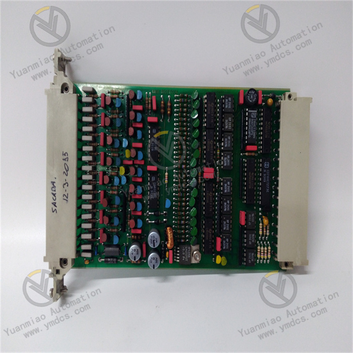
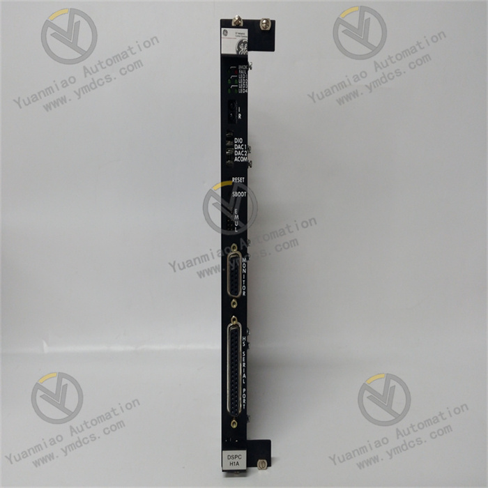
GE 531X305NTBAPG1 | Turbine and Excitation Control Systems

GE 531X305NTBAPG1 | Turbine and Excitation Control Systems

Brand: General Electric

Product ID: 531X305NTBAPG1

Condition: New / used

Terms of payment: Paypal、T/T 、Western Union

Category:

Description

GE 531X305NTBAPG1

I. Overview


The GE 531X305NTBAPG1 is a high-reliability digital I/O module developed by General Electric (GE) for mid-to-high-end industrial control scenarios. It belongs to mainstream industrial control systems such as GE Mark VIe, Fanuc Series 90-30, and Centurion, with its core positioning as a "unit for accurate acquisition of multi-scenario digital signals, safe interlocking, and efficient control execution in complex industrial environments".


This module mainly serves fields with strict requirements for signal stability, system compatibility, and fault tolerance, including energy and chemical industry (e.g., valve control of refining plants, status monitoring of oil and gas transmission pumps)rail transit (signal interaction of train braking systems, status feedback of track switches)high-end manufacturing (interlocking of precision machine tools, signal switching of workstations in automated production lines), and municipal infrastructure (control of water supply pump stations, gate status management of sewage treatment plants). It undertakes the full-process core tasks of "real-time acquisition of on-site digital signals (sensor status, equipment start-stop feedback) - local logic operation and safety interlock judgment - accurate output of control commands (driving actuator actions) - active reporting of equipment faults".


With the core advantages of "high redundancy design + wide-range environmental adaptation + cross-system compatibility + intelligent fault diagnosis", the GE 531X305NTBAPG1 can not only meet the "high density and low latency" requirements of digital I/O modules for newly-built industrial control systems but also seamlessly replace traditional relay components or low-reliability I/O modules in old systems. It effectively solves the four major pain points in industrial control: "strong interference in signal transmission", "module instability in extreme environments", "poor compatibility in system upgrades", and "low efficiency in fault troubleshooting". Through enhanced electromagnetic shielding, selection of wide-temperature components, and standardized interface design, it achieves a signal acquisition response time of ≤ 0.8ms and an output command execution delay of ≤ 4ms, ensuring the continuous and stable operation of industrial systems and reducing production interruption losses caused by module failures (a single interruption can result in losses of up to several hundred thousand yuan).


II. Technical Parameters


(I) Digital Signal Processing Parameters


CategorySpecific Parameters
Digital Input ChannelsNumber of channels: 24 isolated digital inputs (divided into 3 groups, 8 channels per group, supporting independent group configuration).
Input type: Dry contact/wet contact adaptive switching (no hardware jumper required, configured via software).
- Dry contact: Passive contact signal, contact capacity ≥ 2mA@24V DC (to ensure reliable triggering).
- Wet contact: Active signal, voltage range 9-30V DC (wide voltage adaptation), input current 4-28mA.
Response time: ≤ 0.8ms (from signal triggering to module recognition, supporting high-speed signal capture such as emergency stop and fault signals).
Isolation method: Electrical isolation between channels (isolation voltage ≥ 3000Vrms), double isolation between input circuit and control circuit (isolation voltage ≥ 3000Vrms) to suppress ground loop interference and signal crosstalk.
Digital Output ChannelsNumber of channels: 12 isolated digital outputs (divided into 3 groups, 4 channels per group, supporting group control).
Output type: Relay output (Single-Pole Double-Throw, SPDT), compatible with AC/DC loads.
Output capacity: Maximum load current 3A per channel (resistive load), 1.5A per channel (inductive load, external freewheeling diode required).
Output voltage range: AC 120/240V, DC 24/48V (wide voltage adaptation).
Response time: ≤ 4ms (from command issuance to output action).
Isolation method: Electrical isolation between channels (isolation voltage ≥ 3000Vrms), isolation between output circuit and control circuit (isolation voltage ≥ 3000Vrms) to prevent module breakdown by reverse load voltage.
Logical Operation PerformanceProcessor: Built-in 32-bit industrial-grade microprocessor (GE customized model, main frequency ≥ 80MHz).
Operation cycle: ≤ 8ms (completing 24-channel input signal recognition, logical operation, and 12-channel output command generation in a single cycle).
Supported logical functions: AND/OR/NOT/XOR/XNOR logic, delay (adjustable 0.05s-200s), pulse counting (maximum counting frequency 10kHz), edge detection (rising/falling/both edges triggering), multi-channel interlocking (up to 12 input interlocking logics).
Storage capacity: 128KB EEPROM (storing configuration parameters and logical programs, data retained permanently after power failure), 32KB RAM (running cache to improve operation efficiency).

(II) System Interface and Communication Parameters


CategorySpecific Parameters
System Bus InterfaceCompatible buses: GE Genius Bus, PROFIBUS DP, Modbus RTU (automatically adapted according to system configuration, supporting hot switching of bus protocols).
Bus rate: Up to 18Mbps (PROFIBUS DP mode), data transmission delay ≤ 12ms (ensuring real-time interaction with the upper computer).
Bus functions: Supports slave mode, receives control commands from upper computers (e.g., GE Mark VIe controller, Fanuc 90-30 PLC), and uploads 24-channel input status, 12-channel output status, module operating parameters, and fault information.
Address configuration: Bus address (1-64 configurable) set via DIP switch on the top of the module, supporting automatic address conflict detection (bus indicator flashes and reports fault code in case of conflict).
External InterfacesSignal interfaces: 6 groups of Phoenix terminals (5.08mm pitch) on the front panel, corresponding to Input Group 1 (Terminals 1-8), Input Group 2 (Terminals 9-16), Input Group 3 (Terminals 17-24), Output Group 1 (Terminals 25-28), Output Group 2 (Terminals 29-32), and Output Group 3 (Terminals 33-36). Screw-fastened wiring (torque 0.5N・m), contact resistance ≤ 15mΩ.
Status indicators: 24 input status lights (green, steady on = signal valid, flashing = edge triggered, off = no signal), 12 output status lights (red, steady on = output activated, flashing = output abnormal), 1 power light (yellow, steady on = normal power supply, flashing = unstable power supply), 1 bus light (blue, steady on = communication fault, slow flashing = normal communication, fast flashing = data transmission in progress).
Debugging interfaces: 1 USB Type-C interface (compatible with USB 2.0) + 1 9-pin RS-485 serial port (baud rate adjustable 9600-115200bps, data bit 8, stop bit 1, supporting odd/even/no parity), used for local parameter configuration, logical program download, fault log reading, and online debugging.
Module Interconnection- Supports multi-module cascading (up to 16 modules distinguished by bus addresses). After cascading, it can be expanded to 384 inputs / 192 outputs, adapting to multi-node control of large equipment (e.g., multi-plant interlocking control in refineries).
- Supports cooperative work with GE's same-series analog modules (e.g., 531X308 series) and temperature modules (e.g., 531X310 series) via system bus to realize linkage control such as "analog threshold triggering digital output" and "temperature exceeding limit interlocking to cut off load".

(III) Physical and Environmental Parameters


CategorySpecific Parameters
Physical SpecificationsDimensions: 210mm (length) × 135mm (width) × 40mm (height), conforming to GE standard I/O module dimensions, compatible with 35mm DIN rail mounting.
Weight: Approximately 420g.
Installation method: DIN rail clamping (supporting horizontal/vertical installation). Installation gap requirements: ≥ 25mm above and below (for heat dissipation), ≥ 15mm left and right (for wiring and ventilation), ≥ 10mm front and rear (for signal isolation).
Environmental AdaptabilityOperating temperature: -40℃~+75℃ (industrial wide temperature range), no preheating required for startup at -40℃ (startup time ≤ 15s).
Storage temperature: -60℃~+90℃.
Humidity: 5%~98% RH (non-condensing, conforming to IEC 60068-2-3 standard).
Vibration resistance: 15g (10Hz-2000Hz, conforming to IEC 60068-2-6), adapting to high-vibration equipment such as fans, compressors, and rolling mills.
Shock resistance: 60g (1ms pulse, conforming to IEC 60068-2-27), withstanding instantaneous shock during equipment handling and maintenance.
Electromagnetic Compatibility (EMC): Conforming to EN 55022 Class A, EN 55024, and IEC 61000-6-2 standards. ESD protection: ±15kV (air discharge) / ±10kV (contact discharge). Radio frequency radiation immunity: 30V/m (80MHz-1GHz). Radio frequency conduction immunity: 15V (150kHz-80MHz).

(IV) Power Supply and Reliability Parameters


CategorySpecific Parameters
Power Supply RequirementsSupply voltage: 24V DC (±20%), input range 19.2V-28.8V DC.
Operating current: ≤ 500mA (full configuration, 24 inputs fully activated + 12 outputs fully loaded with 3A).
Power protection: Overvoltage protection (automatically cuts off input when ≥ 32V DC), overcurrent protection (triggers current limiting when ≥ 800mA), reverse connection protection (prevents reverse connection of power positive and negative poles, built-in self-recovering fuse 2A), surge protection (differential mode 2kV, common mode 4kV, conforming to IEC 61000-4-5).
Power consumption: ≤ 12W (24V DC × 500mA), adapting to limited power supply resources on industrial sites.
Reliability IndicatorsMean Time Between Failures (MTBF): ≥ 500,000 hours (Telcordia SR-332 standard, 25℃, full configuration operation).
Design life: ≥ 20 years.
Key components: Microprocessors, optocouplers, and relays adopt military-grade wide-temperature models (operating temperature -40℃~+85℃), with gold-plated pins (corrosion resistance rate ≤ 0.08μm/year).
Relay output life: ≥ 1,000,000 switching operations (under rated load), ≥ 10,000,000 switching operations (under light load, ≤ 0.5A).
Fault diagnosis: Built-in hardware-level + software-level dual fault detection circuit, supporting fault detection of power supply abnormality, bus interruption, input channel disconnection/short circuit, output overload/short circuit, relay sticking, etc. Fault codes are reported via indicators, bus, and debugging interface (e.g., "E02 = Under-voltage of power supply", "E10 = Output relay sticking").


III. Functional Features


(I) High Reliability and Redundancy Design, Ensuring Stable System Operation

  • Dual Isolation and Enhanced Anti-Interference: Input/output channels all adopt 3000Vrms dual electrical isolation, combined with nano-level three-proof paint (waterproof, dustproof, anti-corrosive) coating on the circuit board. In coastal chemical workshops with high humidity and high salt spray, and metallurgical plants with strong electromagnetic interference, the annual failure rate of the module can be controlled within 0.1%. Meanwhile, the power module is equipped with a three-stage EMC filter circuit (common mode rejection ratio ≥ 90dB), and when installed next to high-power frequency converters above 300kW, the input signal misjudgment rate is ≤ 0.0005%.

  • Redundant Configuration of Key Components: Built-in dual-channel power supply interfaces (supporting automatic main-standby switching, switching time ≤ 1ms); when one power supply fails, the other can take over seamlessly to avoid module shutdown due to power interruption. The output relays adopt dual-coil design; when a single coil fails, the backup coil can be activated temporarily to ensure the continuous operation of the core control circuit.


(II) Intelligent Adaptation and Efficient Control, Improving System Flexibility

  • Adaptive Adjustment of Input and Output: Digital inputs support software-adaptive switching between dry contacts and wet contacts, without on-site adjustment of hardware jumpers, adapting to different types of sensors (e.g., dry-contact limit switches, wet-contact proximity switches). The output channels are compatible with AC/DC loads, and the output mode (normally open/normally closed) can be switched via software settings, without the need for additional module replacement or relays.

  • Local Intelligent Logic Operation: Relying on a 32-bit high-performance microprocessor, it supports complex logic operations such as 12-channel input interlocking, pulse counting, and delay triggering. It can complete "multi-condition combined control" locally (e.g., "high liquid level alarm + high pressure alarm" interlocking to close the feed valve), without relying on the computing power of the upper computer. This reduces system communication load, with a total control command delay of ≤ 12ms, meeting the real-time requirements of high-speed production lines and equipment safety interlocking.


(III) Cross-System Compatibility and Convenient Upgrading, Reducing Operation and Maintenance Costs

  • Full-Scenario System Adaptation: Perfectly compatible with GE-series control systems such as GE Mark VIe, Fanuc 90-30, and Centurion, and supports programming software such as GE Proficy Machine Edition and Fanuc Ladder Master. It can directly call the module's built-in function blocks (DI acquisition block, DO output block, interlocking logic block), shortening the programming cycle by 60% compared with traditional solutions. It is also compatible with third-party systems such as Siemens S7-1200/1500 and Rockwell ControlLogix, realizing cross-brand interconnection via PROFIBUS DP or Modbus RTU bus, and solving compatibility problems in the upgrading of old systems.

  • Seamless Replacement and Rapid Debugging: Its dimensions and installation interfaces are compatible with GE's old digital modules (e.g., 531X302, 531X304 series), which can directly replace old modules while retaining the original wiring and system programs, reducing the upgrade cost by 50%. Equipped with a USB Type-C debugging interface and visual configuration software, it supports one-click import/export of parameters, online modification of logical programs, and automatic analysis of fault logs. The module debugging time is shortened from an average of 4 hours to 30 minutes.


(IV) Visual Operation & Maintenance and Intelligent Diagnosis, Improving Fault Handling Efficiency

  • Comprehensive Status Monitoring: 38 high-brightness status indicators (24 inputs + 12 outputs + 1 power + 1 bus) are installed on the front panel. On-site operation and maintenance personnel can quickly judge the module's operating status through the color and flashing state of the indicators—for example, "an input light flashes but the sensor has no action" indicates line interference; "the output light is steady on but the load does not work" indicates a relay fault. At the same time, it supports real-time viewing of module temperature, power supply voltage, bus load rate and other operating parameters through the upper computer, realizing preventive maintenance.

  • Efficient Fault Location and Handling: Built-in fault log storage function, which can record the latest 200 fault information (including fault type, occurrence time, fault code, and recovery measures), and supports log export via debugging interface or bus. For common faults (e.g., input disconnection, output short circuit), the module will automatically trigger protection mechanisms (e.g., cutting off the faulty output channel) and report the specific fault location and solution suggestions. The fault location time is shortened from an average of 1.5 hours to 15 minutes, greatly reducing production interruption time.


IV. Common Faults and Solutions


Common Fault PhenomenaPossible CausesSolutions
No signal acquisition from all input channels, all input indicators off1. Abnormal total power supply of the module (power not connected or power voltage outside the range of 19.2V-28.8V).
2. Loose or disconnected wiring of the common terminal in the input circuit.
3. Fault of the module's power supply module.
4. Fault of the module's core processor.
1. Use a multimeter to detect the power supply voltage, ensure the voltage is within the range of 19.2V-28.8V DC, and check whether the power wiring terminals are fastened.
2. Check the wiring of the common terminal (COM terminal) in the input circuit, re-plug and fasten the terminals

contact us