")
")
Description
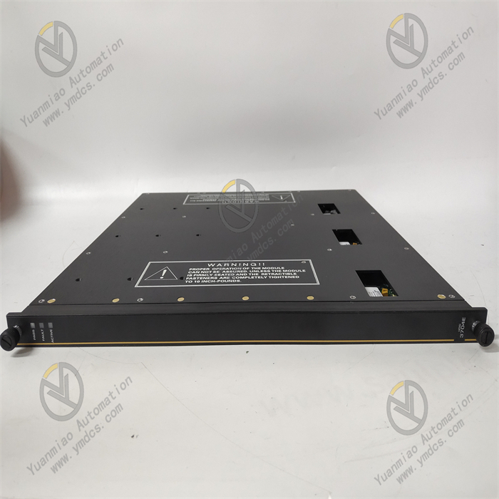
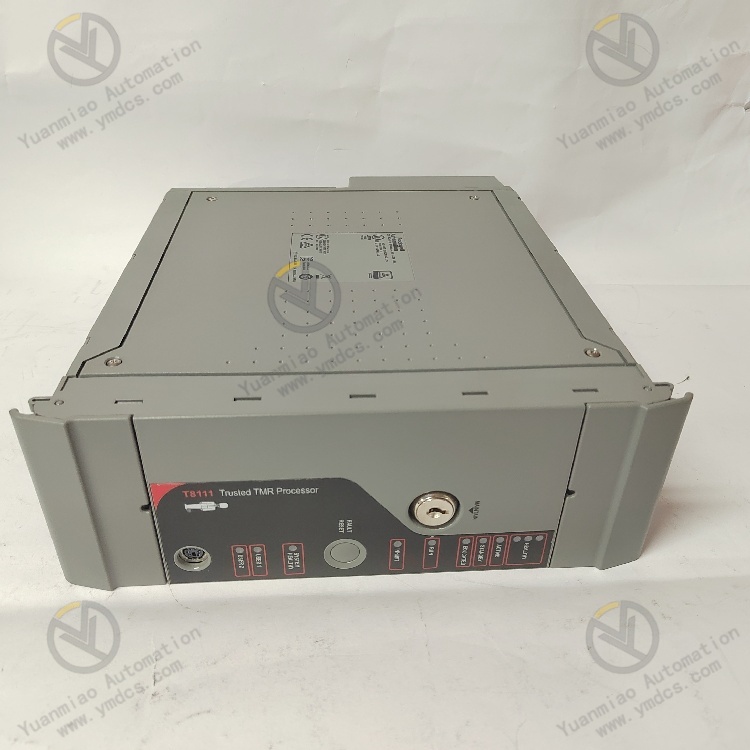
ICS Triplex T8111C
Functional Features
- Multi-Channel Input: Typically equipped with multiple digital input channels, which can connect to different sensors or digital signal sources to simultaneously collect and process multiple signals.
- High-Resolution Acquisition: Equipped with a high-resolution analog-to-digital converter (ADC) to ensure the accuracy and precision of digital signal acquisition, meeting high-precision measurement requirements.
- Diverse Signal Types: Supports various digital signal types such as switch states, pulse counts, and digital sensor outputs, suitable for different application scenarios.
- Configurable Sampling Rate: Users can adjust the sampling rate according to actual needs to optimize system performance and response speed.
- Real-Time Monitoring and Alarming: Capable of real-time monitoring of the status and values of digital input signals. Alarm and trigger conditions can be configured to trigger alarms or events when signals reach preset thresholds, ensuring stable system operation.
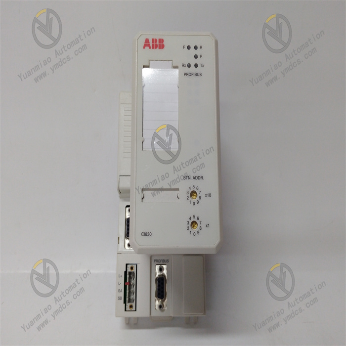
- Multiple Communication Interfaces: Equipped with various communication interfaces such as Ethernet, Modbus, and Profibus, facilitating data exchange and communication with control systems or monitoring systems.
- Data Recording Function: Can record historical data of digital input signals for subsequent analysis and review, helping to optimize system performance and troubleshoot faults.
- Industrial-Grade Design: Adopts industrial-grade design with high durability and reliability, capable of adapting to various industrial environmental conditions such as high/low temperatures, humidity, and vibration. In some applications, it also has power control functions to control and regulate the operation of power equipment, achieving stable power system operation and power adjustment.
Technical Parameters
- Operating Voltage: Input voltage is generally 24VDC; output voltage varies by function (e.g., signal converters may be 0-10VDC).
- Operating Temperature: Can operate in a wide temperature range of -40°C to 85°C.
- Humidity Range: 0% to 95%.
- Power Consumption: 3.0W.
- Dimensions: 263mm×58mm×28mm.
- Weight: 4.3kg.
- Communication Interfaces: Features multiple interfaces such as Ethernet, Modbus, and Profibus, as well as serial ports like RS-232 and RS-422/485.
- Certification: Complies with IEC 61508 SIL 3 certification.
Working Principle
As a processor module based on the Triplex Modular Redundancy (TMR) architecture in the ICS Triplex series, the T8111C operates as follows:
- Signal Input: Receives signals from different sensors or digital signal sources through multiple digital input channels, which can be various types such as switch states, pulse counts, and digital sensor outputs.
- Data Processing: The three processors inside the module (located in the Processor Fault Containment Region, FCR) independently process the input signals, operating in lockstep synchronization mode to ensure processing consistency. Each processor has its own memory and related logic circuits, achieving monitoring and control of industrial process parameters through operations such as analysis, conversion, and calculation of input signals.
- Voting and Fault Tolerance: Adopts a 2-out-of-3 (2oo3) voting mechanism, where the three processors process the same data and determine the final output result through comparison and voting. If one processor fails, the system can still operate normally as long as the results of the other two processors are consistent, thus achieving fault tolerance and improving system reliability and stability.
- Communication and Output: Processed data can be exchanged with other devices or systems through multiple communication interfaces (e.g., Ethernet, Modbus, Profibus). Meanwhile, control signals can be sent to external devices via digital or analog output channels to achieve precise control of industrial processes.
Operation Guide
- Installation: Select an appropriate installation location to ensure the module is firmly installed. Follow the manual to connect power, communication interfaces, and other related devices, paying attention to the correctness and stability of wiring.
- Configuration: Use corresponding configuration software to connect to the module via communication interfaces and set parameters such as communication parameters, sampling rate, alarm parameters, and control parameters to meet specific application requirements.
- Daily Operation: Operators can obtain the collected and processed data through the module's communication interfaces via relevant monitoring systems or devices, and view equipment operation status information and alarm prompts. Adjust parameters and issue commands to the module through configuration software or the host computer system as needed.
- Maintenance and Troubleshooting: Regularly inspect the module's operation status, including communication integrity, data acquisition accuracy, and output control effectiveness. In case of faults, refer to the manual for troubleshooting and repair based on the module's alarm information, indicator light status, and system logs. For complex faults, contact professional technicians for maintenance. Additionally, since the module supports hot-swapping, it can be replaced while the system is running to minimize downtime.
Common Faults and Solutions for ICS Triplex T8111C
Communication Faults
- Fault Phenomenon: The module cannot normally transmit data with other devices, such as failing to establish connections with PLCs or host computers, or experiencing erroneous or interrupted data transmission.
- Causes:
- Communication Line Issues: Poor connections, open circuits, or short circuits in the connection lines.
- Signal Interference: Strong electromagnetic interference sources in the surrounding environment affecting signal transmission.
- Incorrect Module Settings: Mismatched communication parameter settings (e.g., baud rate, data bits, stop bits, parity) with other devices.
- Module Hardware Faults: Damaged communication interfaces or internal communication circuits in the module.
- Solutions:
- Check communication lines to ensure secure connections without damage, open circuits, or short circuits; replace lines if necessary.
- Shield communication lines and keep them away from strong electromagnetic interference sources (e.g., large motors, transformers).
- Carefully verify that the module's communication parameters match those of other devices.
- If hardware faults are suspected, replace the module and contact professional maintenance personnel to repair the faulty module.
Power Supply Faults
- Fault Phenomenon: The module fails to start normally, or experiences abnormal restarts, freezes, or unlit/flickering indicator lights during operation.
- Causes:
- Abnormal Input Voltage: Voltage outside the module's operating range, caused by power supply failures or grid voltage fluctuations.
- Power Line Faults: Poor power line connections, open circuits, or short circuits, leading to unstable power supply to the module.
- Internal Power Circuit Faults: Damaged power chips, capacitor leakage, etc.
- Solutions:
- Use a multimeter to measure input voltage and ensure it falls within the module's specified operating range (e.g., 24VDC±10%). If voltage is abnormal, check power supply devices (e.g., adapters, UPS) or contact the power supply department to address grid voltage issues.
- Inspect power lines, repair or replace damaged cables, and ensure reliable connections.
- If internal power circuit faults are confirmed, contact professional maintenance personnel for repair or module replacement.

Processor Faults
- Fault Phenomenon: The module runs slowly, experiences program errors, freezes, or fails to execute control tasks normally.
- Causes:
- Overheating: Poor heat dissipation leading to excessively high processor temperatures, degraded performance, or faults. This may be due to inadequate ventilation at the installation location or high ambient temperatures.
- Hardware Damage: Faults in the processor chip itself, caused by long-term use, static electricity, power surges, etc.
- Software Issues: Program errors, vulnerabilities, or compatibility problems with the module, leading to abnormal processor execution.
- Solutions:
- Check the module's installation location to ensure sufficient space for heat dissipation, and clean dust and debris from the cooling channels. If ambient temperature is too high, consider cooling measures such as installing air conditioners or fans.
- Perform hardware diagnostics on the module (e.g., use professional tools to check processor status and power voltage). If hardware damage is confirmed, replace the module or contact the manufacturer for repair.
- Review program code to fix errors and vulnerabilities, and update the software to the latest compatible version. Optimize the program to reduce processor load.
Input/Output Faults
- Fault Phenomenon: Digital input channels fail to correctly detect signal state changes; analog input channels collect inaccurate data; digital output channels cannot control external devices; analog output channels emit abnormal signals.
- Causes:
- Sensor or Actuator Faults: Malfunctions in sensors or actuators connected to the module's I/O channels, leading to abnormal signal transmission.
- Channel Configuration Errors: Incorrect parameter settings for I/O channels (e.g., input signal type, range, output signal type, range) that do not match the actual connected devices.
- Channel Hardware Faults: Damage to the module's I/O channel circuits, possibly caused by overvoltage, overcurrent, static electricity, etc.
- Solutions:
- Inspect the working status of sensors and actuators, and use tools like multimeters to measure their output signals. Replace faulty sensors or actuators.
- Carefully verify the configuration parameters of I/O channels to ensure consistency with the actual connected devices.
- If hardware faults are suspected, compare the faulty channel with other normally working channels. If hardware issues are confirmed, contact professionals for repair or module replacement.