Description
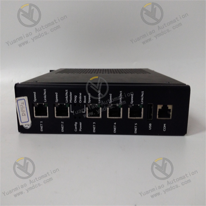
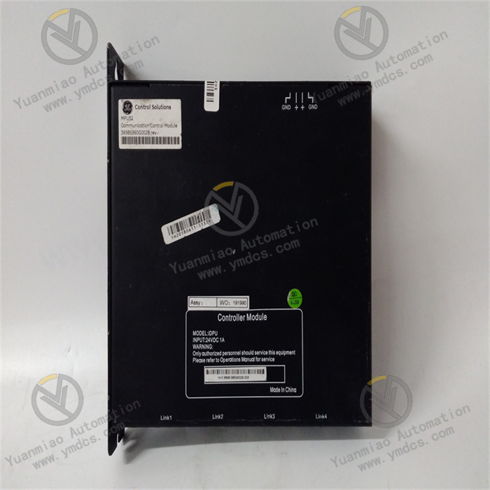
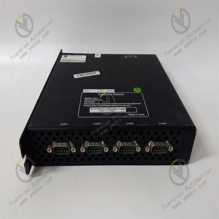
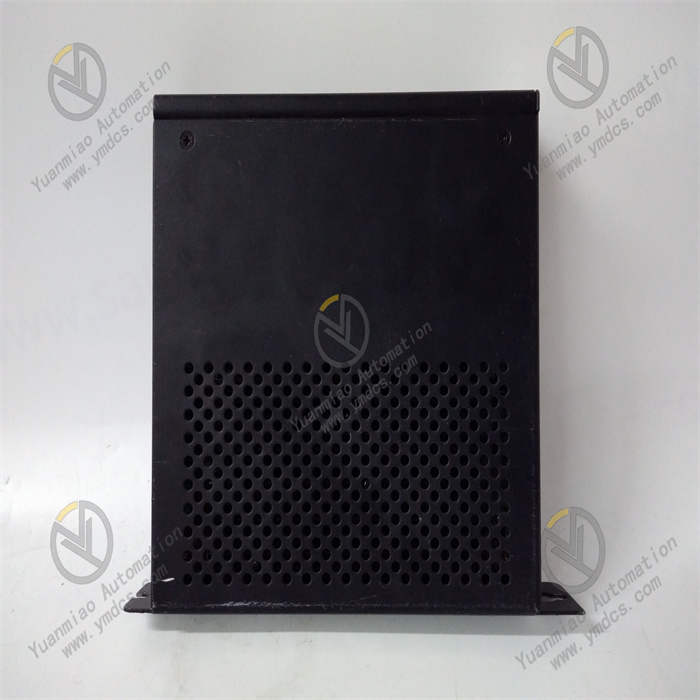
GE 369B1860G0028
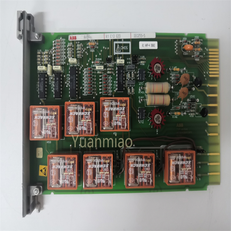
The GE 369B1860G0028 is a control relay module specifically designed for high-reliability automated control systems in fields such as power generation, petrochemicals, and metallurgy. Its core positioning is to implement logical control, signal conversion, and safety interlocking functions for industrial equipment. As a key intermediate component connecting on-site sensors/actuators to upper-level control systems (e.g., PLC, DCS), its core function is to receive discrete or analog input signals, process them through built-in logic circuits for signal judgment, delay, interlocking, etc., and then output control signals to drive executive components such as contactors and valves, ensuring the stability and safety of industrial production processes.
This module adopts a modular design and is compatible with GE control system series such as Mark VIe and Mark V. It features industrial-grade characteristics including wide temperature adaptability (-40℃ to +70℃) and high anti-interference capability (compliant with IEC 61000-4 series standards), and has obtained authoritative certifications such as UL, CE, and CSA. With a channel configuration of 8 inputs/4 outputs per module and a signal response time of ≤1ms, it is widely used in the control circuits of generator sets, large compressors, and power transmission and transformation equipment, serving as a core component for realizing the "monitoring-control-protection" closed loop of industrial equipment.
- Input Channels: 8 independent discrete input channels, supporting dual-voltage adaptation of 24V DC/120V AC, with an input impedance of 2kΩ (DC)/1kΩ (AC). They can directly connect to signals from on-site sensors such as proximity switches and limit switches without the need for additional signal conditioning.
- Output Channels: 4 relay output channels, each with a rated load current of 5A@250V AC/10A@30V DC. They support configurable normally open/normally closed contacts, meeting the requirements for driving executive components such as small motors, solenoid valves, and indicator lights.
- Signal Response: The signal delay from input to output is ≤1ms, supporting high-frequency signal switching (maximum switching frequency of 100 times/second), which is suitable for the control needs of automated production lines with rapid start-stop operations.
- Supply Voltage: 24V DC (with ±10% fluctuation tolerance), compatible with commonly used industrial DC power modules, eliminating the need for dedicated power supply equipment.
- Standby Power Consumption: ≤2W; Power consumption under full load: ≤10W. The low-power design reduces the overall energy consumption of the system and is suitable for emergency control scenarios with battery backup.
- Module Dimensions: 120mm (length) × 80mm (width) × 40mm (thickness), adopting standard 35mm DIN rail mounting. It is suitable for dense layout in industrial control cabinets, saving installation space.
- Weight: Approximately 200g. The lightweight design facilitates module insertion/extraction and maintenance. It supports hot-swapping (when used with a GE dedicated base), allowing replacement without powering off the system, thus reducing system downtime.
- Operating Temperature: -40℃ to +70℃, which is far wider than that of conventional industrial relays (-20℃ to +60℃). It can operate stably in extreme environments such as outdoor control cabinets in frigid zones and high-temperature metallurgical workshops.
- Protection Level: IP20 (module itself); can be upgraded to IP40 when used with a GE dedicated sealed base, effectively isolating dust and a small amount of moisture, making it suitable for dusty environments such as power equipment rooms and petrochemical workshops.
- Anti-interference Performance: Compliant with IEC 61000-4-2 (ESD ±15kV air discharge) and IEC 61000-4-3 (radiated immunity 10V/m) standards. It can maintain stable signals in strong electromagnetic environments such as those with frequency converters and high-voltage motors.
It has built-in overload protection (automatically cuts off when the output current of each channel exceeds 15A) and over-temperature protection (triggers an alarm when the internal temperature is ≥85℃), preventing module burnout and load damage.
- Controller Adaptability: Natively compatible with mainstream control systems such as GE Mark VIe DCS and Fanuc PLC. It communicates with upper-level computers via RS485 (Modbus RTU protocol) and supports remote parameter configuration and status monitoring.
- Expansion Capability: Supports multi-module cascading (up to 32 units). Input and output channels can be expanded via bus expansion, meeting the multi-loop control requirements of large-scale equipment.
It adopts industrial-grade relay contacts (silver alloy material AgSnO₂), which have excellent arc resistance and wear resistance. The mechanical lifespan is ≥10 million operations, and the electrical lifespan is ≥100,000 operations (under rated load). Calculated based on 1,000 switchings per day, the theoretical service life can reach 27 years, significantly reducing the frequency of module replacement and maintenance costs. The module housing is made of flame-retardant ABS material (UL94 V-0 grade), which self-extinguishes when exposed to fire, improving the overall fire safety level of the control cabinet.
It has a built-in programmable logic unit and supports the configuration of "AND/OR/NOT" logic, delay (0.1s to 1000s), pulse output, and other functions through GE Proficy Machine Edition software. Local control logic can be implemented without relying on an upper-level PLC. For example, in generator set control, an interlocking logic of "low oil pressure (Input 1) + high water temperature (Input 2) → shutdown command output (Output 1)" can be configured. The response speed is 50% faster than that of control relying on an upper-level computer, preventing the expansion of faults.
The module panel is equipped with 8 input indicator lights (green), 4 output indicator lights (red), and 1 power indicator light (yellow), enabling intuitive judgment of the working status of each channel. Through the RS485 communication interface, parameters such as the input/output status of each channel, load current, and internal temperature can be read in real time on the upper-level computer. When faults such as contact adhesion and over-temperature occur, fault codes (e.g., "E01: Output 1 overcurrent") are automatically uploaded, facilitating remote diagnosis and rapid troubleshooting and reducing on-site operation and maintenance time.
The ultra-wide operating temperature range of -40℃ to +70℃ and strong anti-interference performance enable it to cover multiple scenarios, from outdoor equipment in northern winters (e.g., power transmission and transformation control cabinets) to high-temperature and high-humidity petrochemical workshops in southern regions. It supports dual-voltage input of 24V DC/120V AC, and can adapt to sensor power supply standards in different regions without replacing the module, reducing the cost of spare parts inventory.
In the auxiliary control system of a gas turbine generator set, the GE 369B1860G0028 serves as the core control module and implements the following functions:
- Signal Acquisition: 8 input channels are respectively connected to signals from the lubricating oil pressure sensor (24V DC), cooling water flow switch (120V AC), and generator stator temperature switch.
- Logical Control: Through built-in logic configuration, functions such as "oil pressure < 0.2MPa (Input 1) → start standby oil pump (Output 1)" and "water temperature > 85℃ (Input 2) → turn on cooling fan (Output 2)" are realized to achieve local emergency control.
- Safety Interlocking: When Input 3 (overspeed switch) and Input 4 (vibration over-limit switch) are triggered simultaneously, Output 3 immediately cuts off the fuel supply valve, and cooperates with the upper-level DCS to achieve dual shutdown protection, preventing damage to the generator set.
In the control circuit of a centrifugal compressor in a catalytic cracking unit of an oil refinery, this module plays the following roles:
- Status Monitoring: Input channels are connected to signals from the compressor inlet pressure switch, bearing temperature switch, and seal gas pressure sensor to monitor the operating status of the equipment in real time.
- Executive Control: Output channels drive the inlet guide vane regulating valve (Output 1), lubricating oil pump (Output 2), and alarm light (Output 3). When the inlet pressure is < 0.5MPa, the guide vane opening is automatically adjusted to maintain stable pressure.
- Fault Response: When the bearing temperature is > 95℃ (Input 5), Output 4 triggers an audible and visual alarm, uploads fault information to the DCS via RS485, and starts the standby cooling system at the same time to prevent bearing burnout.
In the auxiliary system of a rolling mill in a hot-rolled steel plate production line, the GE 369B1860G0028 implements the following functions:
- Roller Table Control: Input channels are connected to signals from the roller table speed sensor (pulse signal) and steel plate position proximity switch (24V DC). Output channels drive the roller table start-stop contactor (Output 1) and steel plate alignment cylinder (Output 2).
- Interlocking Protection: When steel plate position deviation (Input 6) and roller table speed over-limit (Input 7) occur simultaneously, Output 3 immediately stops the operation of the roller table, and Output 4 triggers an emergency stop signal to the main control system to prevent steel plate scratches or equipment collisions.
- Remote Monitoring: The operating status and fault information of the roller table are uploaded to the workshop MES system via the Modbus RTU protocol, realizing visual management of the production process and fault tracing.
- Adopt standard 35mm DIN rail mounting. Reserve a gap of ≥5mm between modules to ensure smooth heat dissipation. If installed in an outdoor or dusty environment, it must be used with a GE dedicated IP40 sealed base to prevent dust from entering the module interior.
- When inserting or extracting the module, operate in the vertical direction along the rail to avoid pin damage caused by tilting. For hot-swapping, disconnect the output load first, then plug in or pull out the power and communication cables to prevent contact burns caused by electric arcs.
- Use 0.5-1.5mm² copper core cables for input and output wiring. A surge suppressor (e.g., RC absorption circuit) must be installed at the relay output end to prevent damage to the module caused by reverse electromotive force generated when inductive loads are powered off.
- Route power cables (e.g., motor cables) separately from module wiring cables (with a gap of ≥15cm). Use shielded twisted-pair cables for input and output wiring (with the shield layer grounded at one end and a grounding resistance of ≤4Ω) to reduce electromagnetic interference.
![]()


