Description
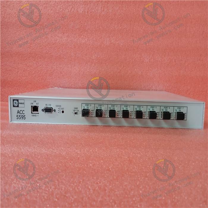
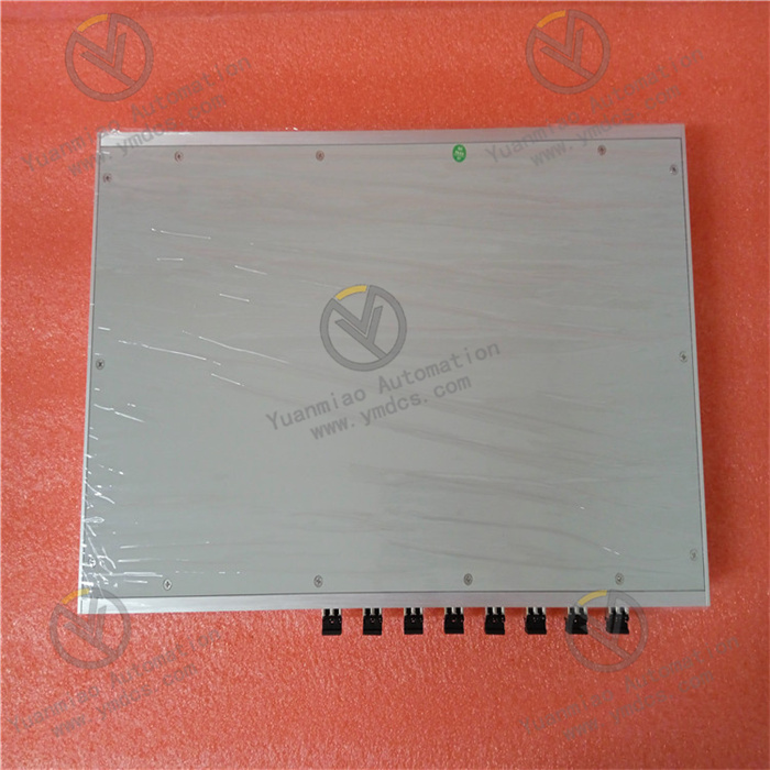
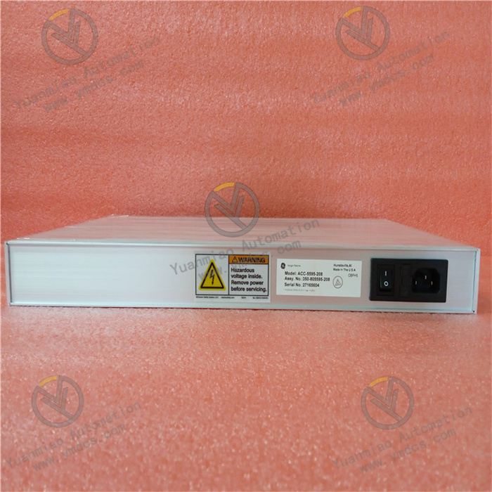
GE ACC-5595-208 350-805595-208N
The GE ACC-5595-208 350-805595-208N is a switching power supply module, serving as an integrated power solution for "main power supply unit - redundant backup - status monitoring" in critical industrial systems such as the Mark VIe Distributed Control System (DCS) and Turbine Control System (TCS). Its design focuses on meeting the strict requirements for power supply continuity in industries including power generation, metallurgy, and oil & gas. Adopting a high-efficiency switching power supply architecture and redundant expansion capability, it can ensure stable power supply for core system modules (e.g., controllers, I/O modules) under extreme scenarios such as grid fluctuations and single-module failures, making it a core component of the "power supply guarantee layer" in industrial control systems.
Compared with general-purpose industrial power supplies, this module has three core advantages: "deep compatibility with GE systems", "high power density", and "full-status monitoring":
- It can be directly embedded into the power supply slot of the Mark VIe standard rack, with an output voltage that accurately matches the power supply requirements of controllers (e.g., PAC8000) and I/O modules (e.g., IC695ALG608) within the system.
- It achieves high-power output in a compact size, adapting to the narrow installation space in industrial sites.
- Meanwhile, it uploads real-time power supply operation data through a communication interface, forming a closed-loop management of "power supply - monitoring - early warning".
- Input Type: Single-channel AC input (supporting multi-module parallel redundancy)
- Input Voltage Range: 100V AC ~ 240V AC (wide-range adaptation, compatible with 110V AC European and American power grids and 220V AC domestic power grids)
- Input Frequency Range: 47Hz ~ 63Hz (adapting to non-standard power frequencies such as diesel generators and UPS)
- Input Current: Maximum input current of 8A (at 110V AC full load), 4A (at 220V AC full load)
- Input Protection: Built-in overvoltage protection (threshold: 264V AC), undervoltage protection (threshold: 85V AC), overcurrent protection (threshold: 10A), and surge protection (differential mode: 2kV, common mode: 4kV)
- Output Voltage: 24V DC ±0.5% (high-precision output, matching the power supply requirements of GE controllers and I/O modules)
- Output Power: Rated output power of 200W (single module), supporting 4-module parallel redundancy (total power up to 800W)
- Output Current: Rated output current of 8.3A (at 24V DC output), peak current of 10A (sustained for 10s)
- Output Protection: Overvoltage protection (threshold: 26.5V DC), overcurrent protection (threshold: 9A), short-circuit protection (constant current limiting mode, no damage), and overtemperature protection (threshold: 75°C, self-recovery when temperature drops to 65°C)
- Voltage Ripple and Noise: ≤20mVpp (at 24V DC output; low ripple ensures the accuracy of analog signal acquisition, e.g., temperature and pressure signal measurement without interference)
- Redundancy Mode: Supports "N+1 parallel redundancy" (up to 4 modules in parallel; when a single module fails, it automatically exits, and the remaining modules share the load equally)
- Current Sharing Accuracy: Current sharing error ≤3% in parallel (ensuring balanced load distribution among modules and extending overall service life)
- Redundant Communication: Realizes status synchronization through a dedicated current-sharing bus between modules, no additional controller intervention required
- Status Monitoring: Real-time monitoring of input voltage/current, output voltage/current, module temperature, and fan speed
- Communication Interface: RS485 interface (Modbus RTU protocol), which can be connected to monitoring software such as GE Proficy iFIX and Intellution Fix
- Alarm Output: 1-channel dry contact alarm output (capacity: 2A/250V AC), corresponding to comprehensive faults of "output overvoltage/overcurrent/overtemperature"
- Parallel Redundancy Architecture: Supports flexible parallel connection of 1-4 modules, adopting "active current-sharing technology" to ensure a load deviation of <3% among modules. When a single module triggers protection due to overtemperature or overcurrent, the remaining modules take over the load without interruption (switching time <1ms), avoiding system power supply interruption (e.g., turbine control system shutdown due to power failure).
- Wide-Range Input Adaptation: The input range of 100V AC ~ 240V AC can adapt to grid fluctuations (e.g., voltage drop to 150V AC during peak power consumption in steel plants), eliminating the need for additional voltage regulators and reducing system integration costs.
- Multiple Protection Mechanisms: Surge protection on the input side can resist instantaneous high voltages caused by lightning strikes and grid switching (e.g., ±4kV common-mode surge). Overvoltage protection on the output side prevents high voltages from damaging GE IC695 I/O modules, forming a triple protection of "input - output - module itself".
- Rack Integration Optimization: The 3U height accurately matches the slot of the Mark VIe standard rack. The output terminals are directly connected to the rack backplane power bus, requiring no additional wiring (e.g., centralized power supply for 8 I/O modules in the rack), simplifying system wiring.
- Precise Voltage Matching: The high-precision output of 24V DC ±0.5% with ripple ≤20mVpp meets the strict requirements of the GE PAC8000 controller for power supply stability (voltage fluctuation ≤±1% to ensure uninterrupted program operation).
- Communication Collaboration and Compatibility: The RS485 interface is preconfigured with the Modbus RTU standard protocol, which can be directly connected to the GE control system monitoring network. It displays 12 operating parameters such as "module output current" and "internal temperature" in real time on the Proficy software interface, realizing collaborative monitoring of power supply status and system status.
- Visual Status Indication: The front panel is equipped with 4 status indicator lights:
- Power indicator (steady green = normal, off = no input)
- Output indicator (steady blue = normal, blinking = overcurrent)
- Fault indicator (steady red = overtemperature/overvoltage, blinking = communication fault)
- Redundancy indicator (steady yellow = redundant operation, off = single-module operation)Basic faults can be quickly located without software.
- Fault Self-Diagnosis Function: Built-in dedicated diagnostic chip that can identify 9 types of faults such as "input undervoltage", "output overcurrent", "module overtemperature", and "fan fault". It sends fault codes (e.g., F01 = input undervoltage, F06 = output overcurrent) to the monitoring system through the RS485 interface, and triggers dry contact alarms to link with sound and light equipment.
- Life Early Warning Mechanism: Real-time monitoring of electrolytic capacitor life and fan speed. When the capacitor capacity decays to 80% of the rated value or the fan speed is lower than 2000rpm, it sends a "maintenance early warning" through the monitoring software, prompting early replacement of spare parts to avoid sudden faults.
- High Conversion Efficiency: AC-DC conversion efficiency ≥88% (at 220V AC full load), which is more than 15% more energy-efficient than ordinary power supplies, reducing the heat load at industrial sites.
- Intelligent Temperature-Controlled Heat Dissipation: Built-in temperature-controlled fan (starts when temperature >40°C, runs at full speed when temperature >50°C). The fan stops when there is no load, extending the fan life to more than 60,000 hours.
- Durable Material Selection: Adopts long-life electrolytic capacitors (life ≥60,000 hours @40°C) and flame-retardant ABS housing (UL94 V-0 grade), adapting to harsh environments such as dust and vibration at industrial sites, with a Mean Time Between Failures (MTBF) ≥150,000 hours.
- Status Monitoring: Check the power supply parameters through the Proficy software daily to confirm that the input voltage is within 180V AC ~ 220V AC (domestic), the output voltage is within 23.8V DC ~ 24.2V DC, the module temperature is <50°C, and there is no fault code alarm.
- Wiring Inspection: Check the input power cables (1.5mm² copper core cables are recommended) and output terminal wiring monthly, and tighten the screws to prevent loosening (increased contact resistance in a vibrating environment may easily cause local overheating).
- Heat Dissipation Maintenance: Clean the dust on the module's heat dissipation holes and fan filter every quarter (blow along the heat dissipation direction with compressed air), and check whether the fan operates smoothly (no jamming or abnormal noise).
- Redundancy Test: Conduct a "single-module power-off test" on the parallel redundant system every six months. Disconnect the input power of one module and observe whether the output current of the remaining modules is evenly distributed (deviation <3%) and the system has no power outage or restart.
![]()


