Description
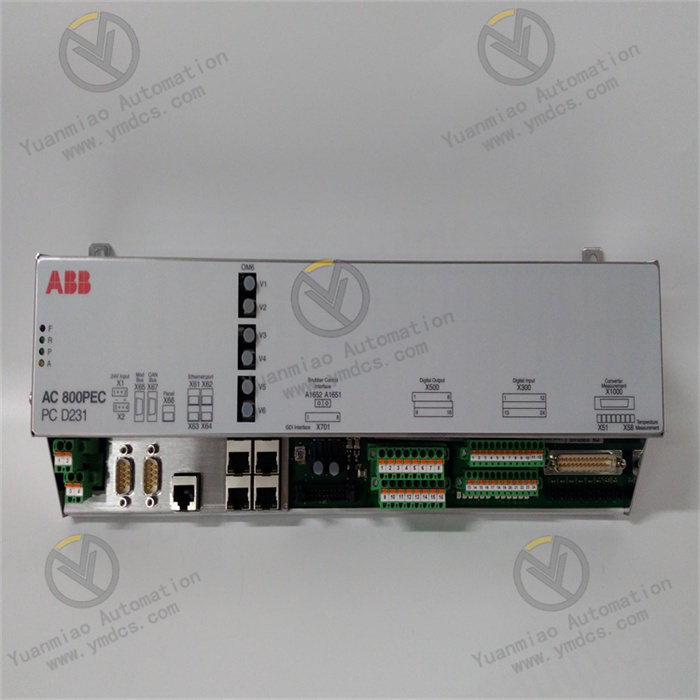
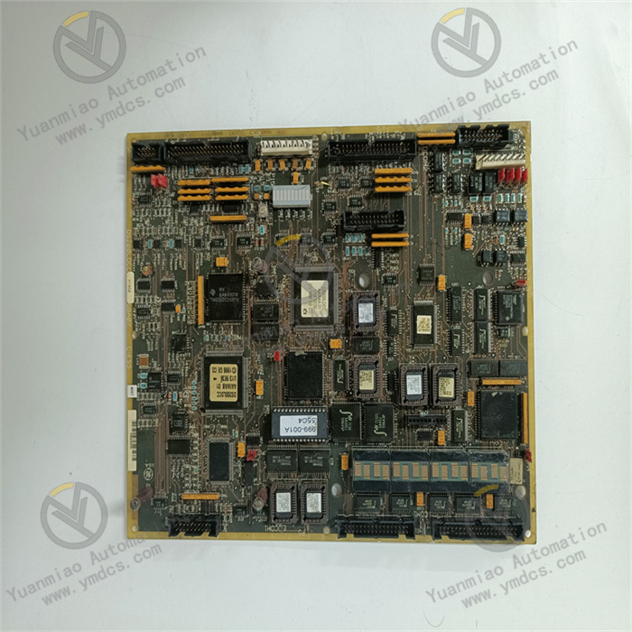
GE IS200ERDDH1ABA
I. Overview
As a key digital I/O component of the Mark VIe system, this module has core advantages of "high-reliability interaction - strong anti-interference isolation - modular compatibility":
- It adopts industrial-grade optocouplers to achieve electrical isolation of input/output signals (isolation voltage ≥2500V AC), resisting electromagnetic interference in industrial sites;
- It supports independent configuration of multiple channels (flexible allocation of input/output) to adapt to signal requirements in different scenarios;
- The modular design supports DIN rail installation and hot swapping, and is highly compatible with the Mark VIe distributed control system and GE Speedtronic turbine management system.
II. Technical Parameters
1. Basic Specifications
| Item | Parameter Details |
|---|---|
| Equipment Type | Mark VIe series digital input/output (I/O) module, used for digital signal acquisition and control output in industrial sites |
| Compatible Systems | GE Mark VIe distributed control system, Speedtronic gas/steam/wind turbine management system |
| Installation Method | DIN rail installation (compatible with 35mm standard rails); compact design; supports hot-swap maintenance |
| Overall Dimensions | Width 45mm × Height 120mm × Depth 110mm (suitable for narrow spaces in control cabinets, with a single module occupying small rail space) |
| Equipment Weight | Approximately 0.3-0.4 kg (lightweight design for easy installation and replacement) |
| Power Supply Requirements | Input voltage: 24V DC ±10% (supports redundant power supply); rated power consumption ≤6W |
| Operating Environment | Temperature: -20°C~65°C (covering industrial high and low temperature scenarios); Humidity: 5%~95% (non-condensing) |
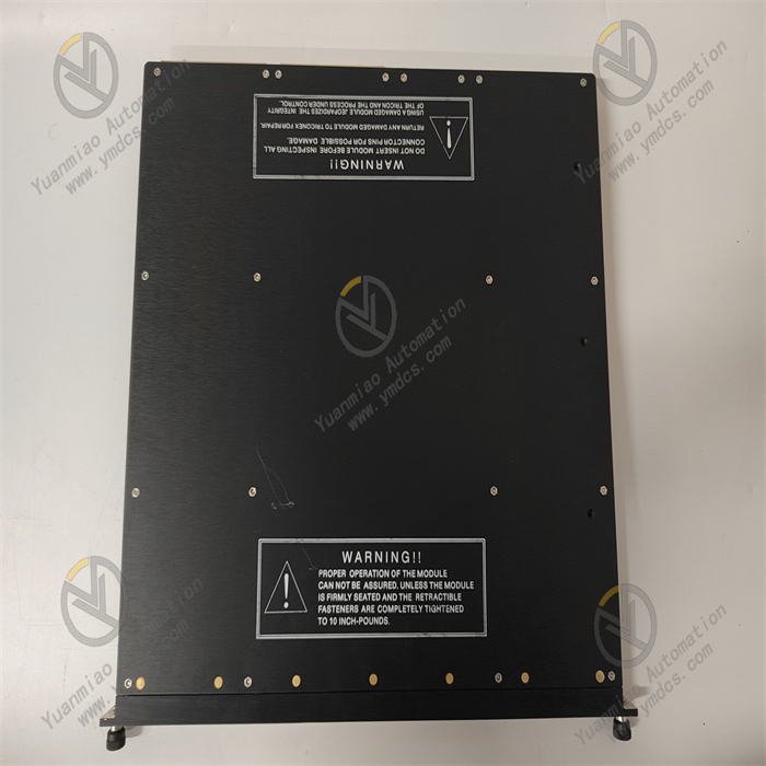
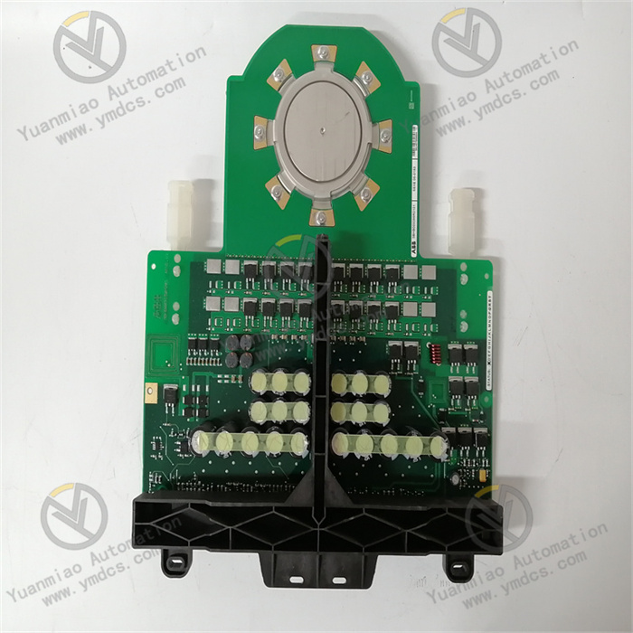
| Protection Design | PCB boards are coated with moisture-proof and anti-corrosion coating; input and output ports have reverse connection protection and short-circuit protection; shell flame retardant rating: UL94 V-0 |
| Storage Environment | Temperature: -40°C~85°C; Humidity: 5%~95% (non-condensing); supports long-term offline storage and transportation |
2. Core Performance Parameters
Digital Input (DI) Characteristics
| Item | Parameter Details |
|---|---|
| Number of Input Channels | 16 independent digital input channels, supporting channel-level fault diagnosis |
| Input Signal Types | Dry contact (on-off signal), wet contact (24V DC level signal, compatible with both NPN and PNP polarities) |
| Input Voltage Range | Low level (0-5V DC, determined as "0"); High level (18-30V DC, determined as "1") |
| Input Current | Maximum input current per channel ≤10mA (for wet contact signals) |
| Response Time | Time from signal level change to module recognition ≤1ms (supports fast state capture, suitable for high-frequency switching signals) |
| Isolation Capacity | Every 4 input channels form a group with isolation; isolation voltage ≥2500V AC for 1 minute |
Digital Output (DO) Characteristics
| Item | Parameter Details |
|---|---|
| Number of Output Channels | 16 independent digital output channels, supporting channel-level overload protection |
| Output Signal Type | Relay output (normally open contact), supporting dry contact control (non-polar) |
| Contact Capacity | Maximum load per channel: 2A @ 250V AC / 3A @ 30V DC (suitable for small and medium-sized actuators) |
| Output Response Time | Time from control command issuance to contact action ≤5ms |
| Protection Function | Each channel has built-in overcurrent protection (self-recovering fuse, rated current 3.5A) to prevent module damage caused by load short circuit |
| Isolation Capacity | Every 4 output channels form a group with isolation; isolation voltage ≥2500V AC for 1 minute |
Communication and Collaboration Characteristics
| Item | Parameter Details |
|---|---|
| Communication Interface | Built-in dedicated Mark VIe backplane bus interface (rate 100Mbps), supporting real-time communication with the system controller |
| Data Transmission Capacity | Digital signal acquisition/output update frequency ≥100Hz; data transmission delay ≤1ms |
| Collaboration Capacity | Highly compatible with Mark VIe system configuration software (e.g., ControlST), supporting online configuration of channel parameters (such as input polarity, output action mode); can be directly connected to GE actuators (e.g., solenoid valves, relays) |
| Fault Diagnosis | Supports channel open/short circuit detection, power undervoltage detection, and communication interruption detection; diagnosis coverage rate ≥99%; fault information is uploaded in real time via the bus |
III. Functional Features
1. High-Reliability Digital Signal Interaction to Ensure Accurate Logical Control
2. Group Isolation and Anti-Interference Design for Complex Industrial Environments
3. Flexible Configuration and Online Operation & Maintenance to Reduce Management Costs
4. Modular Compatibility and Redundant Design to Improve System Availability
5. Adaptation to Harsh Environments to Extend Service Life
IV. Operation, Maintenance, and Troubleshooting
Daily Maintenance Points
- Status Monitoring: Check the status of each channel of the module through the Mark VIe HMI daily to confirm that the DI channel signals are consistent with the on-site equipment (e.g., "valve open" corresponds to DI channel "1") and the DO channel output commands are executed normally (e.g., "pump start" corresponds to DO channel "1") without fault alarms. On-site, check the module's power indicator (steady green), operation indicator (flashing blue), and fault indicator (off red) to ensure the indicators are in normal status.
- Wiring and Contact Inspection: Check the wiring of the module's DI/DO terminals monthly, and re-tighten the screws (torque 0.4-0.6N・m) to prevent wiring looseness caused by vibration (increased contact resistance leading to signal misjudgment). For actuators connected to DO channels (e.g., solenoid valves), check whether the relay contacts are ablated (measure the contact resistance with a multimeter, which should be <1Ω). If ablation is severe, replace the relay or module.
- Function Testing: Conduct "on-off testing" for DI channels quarterly (simulate dry contact signals with jumpers) to verify the module's recognition accuracy. Conduct "no-load testing" for DO channels (disconnect the actuator, measure the contact on-off after outputting commands) to ensure normal output actions. Test the fault protection function (e.g., short-circuit the DO channel to verify whether overcurrent protection is triggered).
- Environment and Cleaning: Clean the dust on the module surface and heat dissipation holes weekly (blow along the heat dissipation direction with compressed air). Check the installation environment temperature monthly (measure the module surface temperature with an infrared thermometer, which should be <60°C) and humidity (avoid condensation). For high-temperature and high-humidity scenarios, enhance ventilation or add dehumidification equipment.
Common Faults and Solutions
| Fault Phenomenon | Possible Causes | Solutions |
|---|---|---|
| No signal acquisition by DI channel (HMI displays "invalid") | 1. Sensor/contact failure; 2. Loose or open wiring; 3. Incorrect channel configuration | 1. Check the status of on-site sensors/contacts (e.g., whether the valve feedback contact is closed) and replace faulty components; 2. Use a multimeter's continuity range to test the cable and re-tighten the wiring; 3. Verify the channel polarity configuration (e.g., NPN/PNP selection) in the ControlST software and reconfigure |
| No output from DO channel (actuator does not act) | 1. Relay contact ablation; 2. DO channel overcurrent protection triggered; 3. Control command not issued | 1. Measure the continuity of the DO terminal; if the contact resistance >10Ω, it indicates ablation, and the module needs to be replaced; 2. Check whether the actuator is short-circuited, and reset the module (power off and restart) after troubleshooting; 3. Check the command issuance status of the Mark VIe controller and re-issue the control command |
| Module reports "power fault" and power indicator is off | 1. Open circuit or reverse polarity of power cable; 2. Redundant power supply switching failure; 3. Module power circuit failure | 1. Measure the 24V DC power supply voltage with a multimeter (should be 21.6-26.4V), and check the cable continuity and polarity (avoid reverse connection); 2. Switch to the backup power supply; if the power indicator is on, the original power supply or switching circuit is faulty; 3. If there is still no response when the power supply is normal, replace the module |
| Simultaneous fault alarm of multiple channels | 1. Group isolation circuit failure; 2. System communication interruption; 3. Abnormal power voltage | 1. Check whether the faulty channels belong to the same isolation group (e.g., Channels 1-4) and replace the module; 2. Check the backplane bus connection and re-plug the module; 3. Measure the power supply voltage and add a voltage-stabilizing power supply if the fluctuation exceeds ±10% |
V. Application Scenarios
- Gas Turbine Safety Interlock Control: In the gas turbine system of a combined-cycle power plant, the module collects 8 channels of safety signals such as "overspeed alarm", "low lubricating oil pressure", and "flame detection" through DI channels, and outputs 4 channels of control commands such as "fuel cut-off", "emergency shutdown", and "alarm trigger" through DO channels. When the DI channel detects an "overspeed" signal (dry contact closed), the module outputs a "fuel cut-off" command within 5ms, and links with the Mark VIe controller to realize emergency shutdown of the gas turbine, avoiding equipment damage.
Auxiliary Equipment Control for Steam Turbines in Thermal Power Plants: In the 600MW steam turbine system, the module collects 12 channels of DI signals (such as condensate pump operation feedback and circulating water pump status) and outputs 8 channels of DO signals (such as pump start-stop commands and valve opening/closing control). Through the Mark VIe system logic, it realizes the automated process of "condensate pump start → outlet valve open → circulating water pump linkage", reducing manual operations and the risk of misoperation.
Wind Turbine Status Monitoring and Control in Wind Farms: In the 2.5MW wind turbine system, the module collects 10 channels of DI signals (such as yaw limit switch and pitch motor brake feedback) and outputs 6 channels of DO signals (such as yaw motor start-stop and pitch brake release). When the DI channel detects a "yaw limit" signal, the module immediately outputs a "yaw motor stop" command to prevent the wind turbine from exceeding the yaw range. The module's wide-temperature design is suitable for the outdoor environment of -20°C~65°C.
Reactor ESD System in Petrochemical Plants: In the emergency shutdown (ESD) system of chemical batch reactors, the module adopts a dual-redundancy configuration, collects 6 channels of DI signals (such as high-pressure alarm contacts and high-temperature alarm contacts), and outputs 4 channels of DO signals (such as feed valve closing and emergency pressure relief valve opening). When any DI channel detects an alarm signal, the dual modules synchronously output ESD commands to ensure safe pressure relief of the reactor, meeting the SIL 2 level requirements.