Description
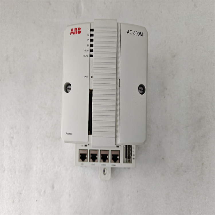
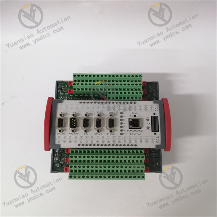
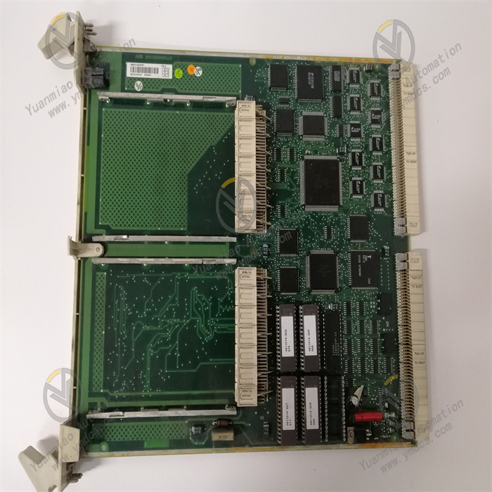
ABB PM866AK02 3BSE081637R1
Basic Information
Brand: ABB
Model: PM861AK02
Order Number: 3BSE081637R1
Type: Industrial automation control module (typically a central processing unit / CPU module for PLC or DCS systems)
Model: PM861AK02
Order Number: 3BSE081637R1
Type: Industrial automation control module (typically a central processing unit / CPU module for PLC or DCS systems)
Functional Features
High-Performance Processing
- Equipped with a 32-bit processor, supporting high-speed data processing and complex control algorithms.
- Suitable for real-time control, logic operations, data acquisition, and processing tasks.
Communication Capability
- Supports multiple industrial communication protocols (e.g., PROFINET, Ethernet/IP, Modbus, etc.), enabling seamless integration with other devices or systems.
- Built-in Ethernet interface for convenient programming, monitoring, and remote maintenance via the network.
Expandability
- Can connect to various I/O modules (e.g., DI/DO, AI/AO, counter modules, etc.) to meet system requirements of different scales.
- Supports redundant configurations (e.g., dual CPU hot standby) to enhance system reliability.
Programming and Configuration
- Compatible with ABB’s Control Builder M programming software, supporting IEC 61131-3 standard programming languages (e.g., Ladder Diagram LD, Structured Text ST, etc.).
- Supports online debugging, program downloading, and firmware upgrades.
Reliability Design
- Industrial-grade hardware adapted to harsh environments (e.g., high temperature, vibration, electromagnetic interference, etc.).
- Features fault diagnosis and self-testing functions, with LED status indicators for real-time operation monitoring.

Technical Parameters
| Parameter | Description |
|---|---|
| Processor | 32-bit microprocessor, clock frequency typically hundreds of MHz (specific to model version) |
| Memory | Built-in RAM and flash memory for storing programs and data (capacity refer to manual) |
| Communication Interfaces | 1-2 Ethernet ports, supporting 10/100 Mbps |
| Power Supply | DC 24V (voltage range: 19.2–30V DC) |
| Operating Temperature | -20°C ~ +60°C (industrial-wide temperature design) |
| Protection Level | IP20 (suitable for installation in control cabinets) |
| Dimensions | Compact design, specific dimensions refer to the product manual (usually standard rail-mounted) |
Supporting Components and Systems
Software: ABB Control Builder M, AC 800M system software
Hardware: I/O modules (e.g., 3BSE series), power modules, communication modules, rails, and accessories
Hardware: I/O modules (e.g., 3BSE series), power modules, communication modules, rails, and accessories
Application Fields
This module belongs to ABB’s AC 800M series controllers and is widely used in:
- Process automation (e.g., chemical, oil & gas, power, water treatment, etc.)
- Machinery manufacturing
- Building automation
- Large equipment control systems

General Operation Guide for ABB PM861AK02
Installation and Connection
DIN Rail Installation: Mount the PM861AK02 controller on a horizontal DIN rail via its base mounting plate, securing it using the sliding and locking mechanism to ensure firm installation.
Power Connection: Connect a 24V DC power supply (voltage range: 19.2–30V DC), ensuring correct positive and negative connections.
Control Network Connection: Connect to the control network via the two RJ45 Ethernet ports (CN1, CN2) on the baseplate for data communication with host computers, other controllers, or related devices. Use the isolated RJ45 serial port (COM4) to connect configuration tools, or the COM3 port (RS-232C port) for devices with modem control signals.
Configuration and Parameter Setting
Hardware Configuration: For CPU redundancy, correctly connect redundant components (e.g., CEX-Bus extension cables, RCU-link cables, etc.) as per the manual, ensuring all components function properly. Connect S800 I/O modules to the corresponding bus as needed and set parameters such as addresses.
Software Configuration: Use the 800xA Control Builder software to configure the PM861AK02. Set various controller parameters in the software, such as communication parameters (Ethernet interface IP address, subnet mask, gateway, etc.), real-time clock parameters, memory allocation parameters, etc. Write control programs (including logic control and process control algorithms) according to specific control tasks and download them to the controller.
Software Configuration: Use the 800xA Control Builder software to configure the PM861AK02. Set various controller parameters in the software, such as communication parameters (Ethernet interface IP address, subnet mask, gateway, etc.), real-time clock parameters, memory allocation parameters, etc. Write control programs (including logic control and process control algorithms) according to specific control tasks and download them to the controller.
Operation and Monitoring
Controller Startup: Power on the controller after installation and configuration. Check its working status via LED indicators (e.g., power indicator, run indicator, communication indicator, etc.). Normally, the power indicator remains on, the run indicator flashes to show the controller is executing programs, and the communication indicator flashes or remains on according to the communication status.
Real-Time Monitoring: Use host computer monitoring software or related operation interfaces to real-time monitor the controller’s running status and data (e.g., CPU usage, memory occupancy, I/O module input/output values, control program execution results, etc.). Set alarm thresholds to trigger timely alerts when parameters exceed normal ranges.
Remote Operation: If the system supports remote control, operate the PM861AK02 via the network (e.g., remotely modify parameters, start/stop control programs, remote reset, etc.).
Maintenance and Fault Handling
Routine Maintenance: Regularly inspect the controller’s operation (e.g., check LED indicators, clean device surfaces, etc.). Check battery status—replace the built-in lithium battery when low or verify the connection and test the performance of external backup batteries periodically.
Fault Diagnosis: When a fault occurs, first check the LED indicators’ status. Based on the flashing pattern or color change, refer to the fault code table in the manual for preliminary cause identification. Use the controller’s built-in diagnostic functions or related software for comprehensive system diagnosis to obtain detailed fault information (e.g., view error logs, diagnostic register values, etc.). Common faults include communication failures, power supply issues, I/O module faults, and program errors. Take corresponding solutions, such as checking communication lines, replacing faulty modules, or correcting program errors.
Fault Diagnosis: When a fault occurs, first check the LED indicators’ status. Based on the flashing pattern or color change, refer to the fault code table in the manual for preliminary cause identification. Use the controller’s built-in diagnostic functions or related software for comprehensive system diagnosis to obtain detailed fault information (e.g., view error logs, diagnostic register values, etc.). Common faults include communication failures, power supply issues, I/O module faults, and program errors. Take corresponding solutions, such as checking communication lines, replacing faulty modules, or correcting program errors.


