Description
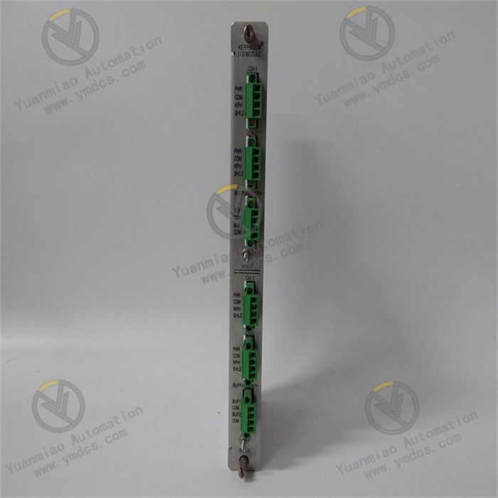
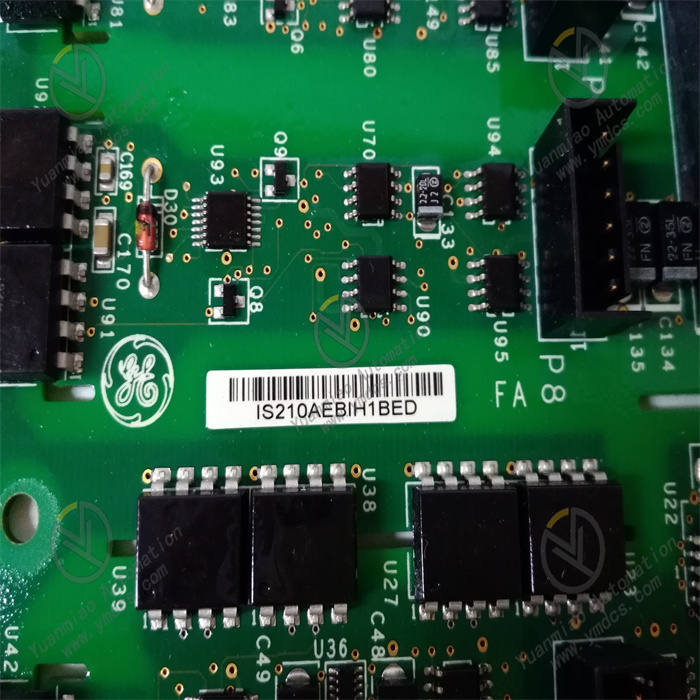
GE IS210AEBIH1BED
I. Overview
II. Technical Specifications
(I) Core Signal Acquisition Parameters
Input Channels and Types
- Number of Channels: 24 independent digital input channels (divided into 3 groups, 8 channels per group, supporting group isolation). Groups work independently and can be connected to signals from different types of equipment (e.g., valve status, pressure alarm, emergency stop signal). When one group of channels fails, it does not affect the operation of other groups, improving the system's fault tolerance.
- Signal Type: Supports dual-mode input of dry contacts/wet contacts. Dry contacts are compatible with passive switches (e.g., mechanical limit switches, relay contacts), and wet contacts are compatible with active signals (e.g., 24V DC proximity sensors, photoelectric sensors). The channel mode can be switched with one click through software without hardware modification, adapting to diverse on-site equipment.
Input Voltage Range:
- Wet contact mode: 24V DC (wide-range adaptation of 19V DC ~ 32V DC), 125V DC/AC (optional voltage adaptation module). It is compatible with on-site equipment of different power supply specifications, reducing signal conversion links.
- Dry contact mode: Supports normally open/normally closed contacts, with contact operating current ≤ 1mA (low-power design to extend switch service life and reduce equipment energy consumption).
- Response Time: ≤ 0.5ms (time from signal triggering to completion of acquisition by the terminal board). It supports edge detection (configurable rising edge/falling edge), which can accurately capture sudden changes in equipment status (e.g., sudden valve closure, emergency stop button activation) and avoid false acquisition caused by signal jitter (e.g., contact bounce during motor start-stop).
Anti-Interference and Signal Processing Parameters
- Isolation Performance: Adopts "three-level electrical isolation (channel-level, group-level, power supply-level)". The isolation voltage between channels is ≥ 500Vrms for 1 minute, between groups is ≥ 1000Vrms for 1 minute, and between power supply and signals is ≥ 2500Vrms for 1 minute. This effectively blocks ground loop interference (e.g., signal crosstalk caused by ground potential differences between different devices) and electromagnetic coupling interference.
Electromagnetic Interference Resistance: Complies with EN 61000-6-2/EN 61000-6-4 industrial immunity standards. It has electrostatic discharge (ESD) protection of ±15kV (air discharge)/±8kV (contact discharge), radio frequency radiation immunity of 10V/m (80MHz ~ 1GHz), and burst immunity of ±2kV (5kHz). In strong interference environments such as high-voltage motors and frequency converters, the signal bit error rate is ≤ 10⁻⁹.
Filtering Function: Built-in dual filtering mechanism of "hardware RC filtering + digital filtering". Hardware RC filtering (10kHz cutoff frequency) filters out high-frequency electromagnetic interference (e.g., signal glitches caused by radio frequency signals), and digital filtering (configurable filtering time of 0.1ms ~ 10ms) eliminates low-frequency signal jitter (e.g., contact bounce of mechanical switches). The signal stability after filtering is ≥ 99.9%.
Transmission and Synchronization Parameters
- Communication Interface: Connected to Mark VIe main controllers (e.g., IS200 series) through GE's dedicated backplane bus. The bus rate is ≥ 100Mbps, and the signal transmission delay is ≤ 1ms (from terminal board to main controller). It supports "clock synchronization" with the controller (synchronization error ≤ 10μs), ensuring the time consistency of signals collected by multiple terminal boards (e.g., valve status and pressure signals collected by different terminal boards can be accurately matched with timestamps).
Data Buffer: Built-in 128KB data buffer, which can temporarily store 800 pieces of signal status data (including timestamps). When the backplane bus is temporarily interrupted (≤ 500ms), data is not lost and will be automatically retransmitted after the bus is restored, avoiding the loss of control logic caused by data disconnection.
- Status Indication: Each channel is equipped with an independent LED indicator (steady green = signal "on", off = signal "off", blinking = signal abnormal). Group-level fault indicators are provided (steady red = fault in the group of channels), facilitating on-site personnel to quickly judge signal status and fault location, and reducing troubleshooting time.
(II) Physical and Environmental Parameters
Physical Specifications
- Dimensions: 220mm (length) × 150mm (width) × 50mm (height) (19-inch 3U rack-mounted, compatible with Mark VIe standard cabinets). Consistent with the size of terminal boards in the same series, it can directly replace old terminal boards (e.g., IS210AEDBH4AGD) without modifying cabinet mounting holes, reducing system upgrade costs.
- Weight: Approximately 0.8kg. The lightweight design supports hot swapping by a single person (replacement time ≤ 2 minutes). When plugging and unplugging, the connection between the terminal board and the backplane bus is automatically disconnected, without affecting the operation of other terminal boards and the entire control system, reducing equipment downtime.
- Terminal Blocks: Adopts spring-loaded quick-connect terminal blocks (compatible with 1.0mm² ~ 2.5mm² wires). No tools are needed for wiring (wires can be fixed by pressing), which improves wiring efficiency by 50% compared with traditional screw terminals. Terminals are arranged in zones (power supply zone, channel zone, bus zone) with clear labels (e.g., "CH1-8", "PWR1+") to avoid equipment failures caused by wiring errors.
Environmental Adaptability
- Operating Temperature: -40℃ ~ +70℃, meeting the operation requirements of extremely cold areas (e.g., outdoor substations in Northeast China) and high-temperature workshops (e.g., near rolling mills in metallurgical plants). No preheating is required for low-temperature startup (-40℃), and the startup time is ≤ 30s. Within the full temperature range of -40℃ ~ +70℃, there is no attenuation in signal acquisition accuracy.
- Humidity: 5% ~ 95% (non-condensing, complying with IEC 60068-2-3 standard). In coastal high-humidity and high-salt-fog environments (e.g., offshore wind power platforms), the circuit board is coated with nano-scale three-proof paint (waterproof, dustproof, anti-corrosive), and the terminals are gold-plated (corrosion rate ≤ 0.1μm/year), ensuring no corrosion or poor contact and long-term stable operation.
Protection Level: IP20 (installed inside the cabinet), compatible with industrial control cabinets with IP54 protection level. It can effectively prevent dust and slight moisture intrusion, adapting to complex environmental conditions of industrial sites.
- Vibration and Shock Resistance: Vibration resistance level of 10g (10Hz ~ 2000Hz, complying with IEC 60068-2-6), capable of withstanding continuous vibration during the operation of turbines and compressors (vibration acceleration ≤ 10g); shock resistance level of 20g (11ms pulse, complying with IEC 60068-2-27), capable of withstanding instantaneous shocks during equipment handling and maintenance, avoiding loosening or damage of internal components.
(III) Power Supply and Reliability Parameters
- Power Supply Requirements: Adopts dual-channel redundant power input (24V DC, terminals marked "PWR1+", "PWR1-", "PWR2+", "PWR2-"). The input current of a single power channel is ≤ 180mA (in full configuration), and the power consumption is ≤ 4.5W. The dual power supplies automatically achieve load balancing; when one power supply fails (e.g., power failure, abnormal voltage), the other takes over seamlessly within ≤ 100μs, ensuring the continuous operation of the terminal board and no risk of signal acquisition interruption.
Reliability Indicators: Mean Time Between Failures (MTBF) ≥ 500,000 hours (Telcordia SR-332 standard, at 25℃), design life ≥ 15 years. Key components (e.g., optocouplers, filter capacitors, relays) are selected with industrial-grade wide-temperature specifications (operating temperature: -40℃ ~ +125℃), ensuring stable performance in extreme environments.
Fault Diagnosis: Built-in "three-level diagnosis function (channel-group-power supply)", capable of detecting more than 10 fault types such as "channel open/short circuit", "group isolation fault", "power supply overvoltage/undervoltage", and "bus communication interruption". The diagnosis coverage rate is ≥ 98%, and the fault detection time is ≤ 100μs. Fault information is uploaded to the main controller through the backplane bus (e.g., "F02=CH10 channel short circuit", "F05=PWR2 power supply undervoltage") and triggers the corresponding indicator alarm, facilitating quick fault location and handling.
III. Functional Features
(I) Highly Reliable Signal Acquisition, Ensuring Control Accuracy
Three-Level Isolation and Dual Filtering, Resisting Complex Interference
Dry/Wet Contact Dual-Mode Switching, Adapting to Diverse Equipment
Millisecond-Level Response and Edge Detection, Capturing Instantaneous Status
(II) Strong Environmental Adaptability and Stable Operation, Reducing Operation and Maintenance Costs
Wide-Temperature and Anti-Corrosion Design, Adapting to Extreme Scenarios
Redundant Power Supply and Fault Self-Recovery, Reducing Downtime
Hot Swapping and Calibration-Free, Improving Operation and Maintenance Efficiency
(III) In-Depth Adaptation and Convenient Management, Optimizing System Integration
Seamless Compatibility with Mark VIe Systems, Reducing Integration Difficulty
Grouped Isolation and Visual Indication, Simplifying Troubleshooting
Remote Status Monitoring, Improving Management Efficiency