Description
I. Functional Features
- High-Performance Control Core
- Multi-Core Processor Architecture: Equipped with an industrial-grade processor (such as ARM or PowerPC), it supports real-time multitasking and can execute complex logic control, motion control, and advanced algorithms, meeting the requirements of high-speed response industrial scenarios (such as robots and precision machinery).
- Real-Time Operating System (RTOS): Ensures the determinacy and microsecond-level precision of control tasks, and supports the rapid processing of sensor signals and actuator commands.
- Floating-Point Unit (FPU): Improves the accuracy of mathematical calculations and is suitable for scenarios that require high-precision control (such as servo motor regulation and process optimization).
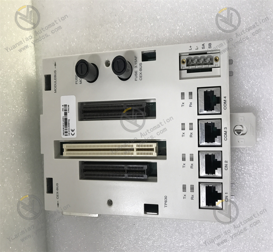
- Rich Communication and Expansion Capabilities
- Integrated Ethernet interface supports mainstream protocols such as PROFINET, Modbus TCP, EtherCAT, and OPC UA, and is compatible with host computers, SCADA systems, and the Industrial Internet of Things (IIoT).
- Supports fieldbuses such as PROFIBUS DP and CANopen, and is suitable for distributed I/O modules (such as ABB's PM500/PM800 series).
- Serial interfaces (RS232/RS485) are used to connect traditional devices or third-party systems.
- Industrial Communication Protocols:
- Distributed System Expansion: Expands a large number of I/O modules through ABB's System 800xA architecture or fieldbus, supporting large-scale control systems (such as hundreds to thousands of I/O points).
- Modularity and Programming Compatibility
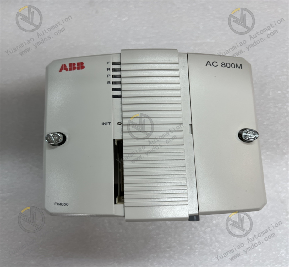
- AC 800M System Compatibility: As the core controller of the AC 800M series, it can be seamlessly integrated with the I/O modules, safety modules, and communication modules of this series to build customized solutions.
- Programming Standards: Supports IEC 61131-3 programming languages (such as Ladder Diagram LD, Structured Text ST, and Function Block Diagram FBD), and uses ABB Control Builder M or AC 800M Library development tools, supporting code reuse and modular design.
- Industrial-Grade Reliability and Safety
- Wide operating temperature range (-20°C to +60°C), adapting to high-temperature, humid, or dusty environments.
- Resistant to vibration and shock (complying with IEC 60068-2 standards), meeting the mechanical stress requirements of heavy industry sites.
- Environmental Adaptability:
- Power Supply and Redundancy: Supports dual-power input (24 VDC redundancy), has reverse connection protection and overvoltage protection, ensuring stable system operation during power fluctuations.
- Functional Safety: Can be equipped with safety modules to achieve SIL 2/3-level safety systems, complying with standards such as IEC 61508 and ISO 13849, and is suitable for safety-critical applications (such as emergency stop and fire interlock).
- Data Management and Diagnosis
- Storage and Logging: Built-in non-volatile flash memory supports the power-off preservation of programs and data; it can record system logs, fault alarms, and operation data, facilitating traceability and maintenance.
- Remote Debugging: Achieves online monitoring (real-time variables and parameter modification) and remote firmware upgrade through Control Builder M, reducing on-site maintenance costs.
II. Technical Parameters
| Parameter | Description |
|---|---|
| Processor | Industrial-grade multi-core processor (such as ARM Cortex-A or PowerPC), with a main frequency of ≥1 GHz |
| Memory | - System memory: 1 GB DDR3 SDRAM - Flash memory: 512 MB (expandable via SD card) |
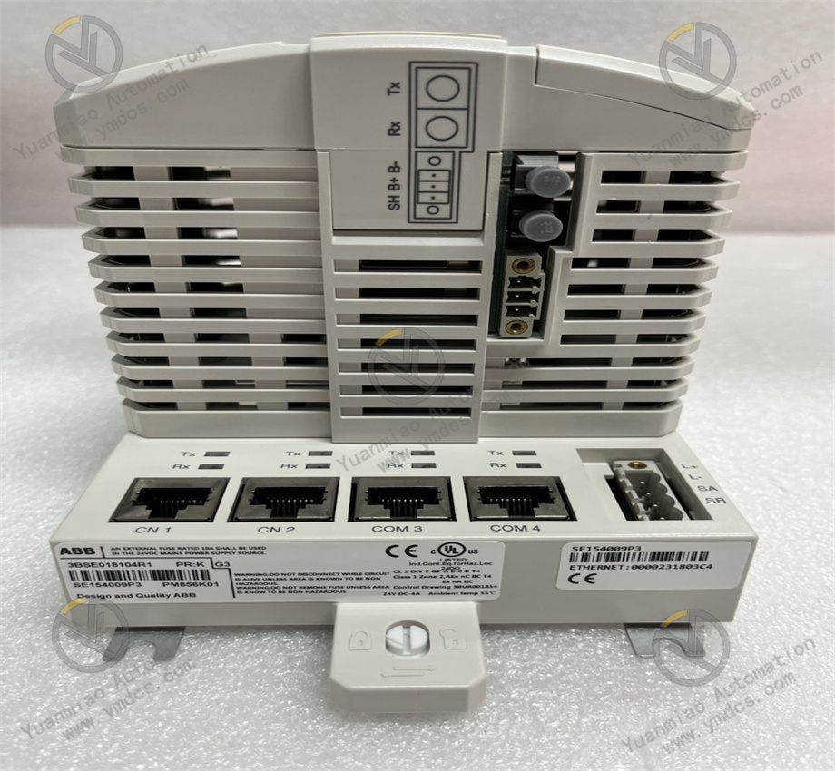
| Communication Interfaces | - Ethernet: 2× 10/100/1000 Mbit/s (RJ45, supporting PROFINET/EtherCAT) - Serial: 1× RS232/RS485 - Fieldbus: PROFIBUS DP master/slave (optional) |
| Input Voltage | 24 VDC (±15%), supporting redundant power input |
| Power Consumption | Typical value ≤15 W (without expansion modules) |
| Operating Temperature | -20°C to +60°C (horizontal installation), -20°C to +50°C (vertical installation) |
| Storage Temperature | -40°C to +85°C |
| Protection Class | IP20 (in rail-mounted state) |
| Dimensions | Approximately 40 mm (width) × 273 mm (height) × 252 mm (depth) |
| Weight | Approximately 1.5 kg |
| Real-Time Clock | Battery-powered, with an accuracy of ±50 ppm (25°C) |
| I/O Expansion Capacity | Supports thousands of I/O points through fieldbus (depending on system configuration) |
| Safety Certifications | IEC 61508, ISO 13849 (requires matching safety modules) |
III. Application Scenarios
- Manufacturing Automation
- Robotics and Motion Control: Used for industrial robot controllers and multi-axis servo systems (such as electronic cams and synchronous control), supporting high-precision positioning and trajectory planning.
- Discrete Manufacturing: Edge control for automotive production lines and electronic assembly lines, accessing the IIoT to achieve device networking, OEE analysis, and predictive maintenance.
- Process Industry
- Chemical and Pharmaceutical: Reactor control, distillation column regulation, and formula management for aseptic filling lines, meeting GMP compliance requirements.
- Power and Energy: Power plant DCS systems, energy conversion control, and remote monitoring for photovoltaic/wind power generation.
- Heavy Industry and Machinery
- Metallurgy and Mining: Rolling mill speed synchronization, mineral processing process automation, and equipment vibration monitoring (such as belt conveyor control).
- Packaging Machinery: Multi-axis synchronization control, servo motor drive, and tension adjustment for high-speed packaging lines.
- Smart Buildings and Energy Management
- Building Automation: Central air conditioning systems, energy metering, and fire alarm systems, supporting building protocols such as BACnet.
- Energy Management System (EMS): Microgrid control, energy storage system coordination, and energy consumption optimization.
IV. Installation and Configuration Highlights
Installation Steps
- Preparation Work:
- Confirm that the environment meets the requirements: Temperature, humidity, and electromagnetic interference (EMC) comply with the specifications, and avoid installing strong magnetic field devices (such as variable frequency drives) in close proximity.
- Tool preparation: Screwdriver, wire stripper, multimeter, and ensure that the power supply meets the 24 VDC requirement (voltage fluctuation ≤±15%).
- Physical Installation:
- Rail Installation: Use a standard DIN rail (EN 50022) and install it in a well-ventilated area of the control cabinet, reserving heat dissipation space (≥50 mm) above, below, left, and right.
- Fixing the Module: Fix it through the 卡扣 or screws at the bottom of the module to ensure firm seismic resistance (refer to the IEC 60068-2 vibration standard).
- Wiring Connection:
- Ethernet: Use CAT5e/CAT6 shielded cables to connect to the switch or host computer. When supporting PROFINET, configure the device name and IP address.
- Fieldbus: PROFIBUS needs to connect a terminal resistor (120Ω), and CANopen needs to set the node address (through module DIP switches or software configuration).
- I/O Expansion: Connect distributed I/O modules (such as ABB DI810 and DO810) through bus cables to ensure the correct bus termination.
- Power Connection: Connect to a 24 VDC redundant power supply, pay attention to the positive and negative poles (usually red is + and black is -), and avoid short circuits.
- Communication Cables:
Configuration Steps
- Hardware Configuration:
- Ethernet: Set the IP address (such as 192.168.1.100), subnet mask, gateway, and when enabling PROFINET, assign a device name (such as "Controller_01").
- PROFIBUS: Set the baud rate (such as 1.5 Mbps) and slave address (when in master mode, configure the slave devices).
- Configure I/O modules: Add the connected distributed I/O modules in the software and assign input/output addresses.
- Open the ABB Control Builder M software, create a new project, and select the controller model PM856K01.
- Configure communication interface parameters:
- Software Installation and Programming:
- Install the controller firmware: Update the firmware to the latest version through Control Builder M or SD card (ensure compatibility).
- Write the control program: Use IEC 61131-3 languages to develop the logic, such as using a ladder diagram to achieve motor start/stop control and structured text to write a PID algorithm.
- Download the program: Download the program to the controller through Ethernet or serial port, and enable the online monitoring function to debug variables.
- Network and Safety Configuration:
- Industrial Network Configuration: When accessing the factory network, set firewall rules and only open the necessary ports (such as port 4840 for OPC UA).
- Safety Function Configuration (if required): When equipped with a safety module (such as SM501), use the Safety Builder M software to write the safety logic and implement the emergency stop path through FBD or ST languages.
- Debugging and Verification:
- Check before power-on: Confirm that the power supply voltage is correct, the wiring is firm, and there is no short-circuit risk.
- Power-on test: Observe the status of the controller indicator lights (such as RUN, ERROR, and COMM lights), and monitor through the software whether it starts normally.
- Function verification: Manually trigger the input signal (such as a button) to check whether the output module action is correct and whether the communication data is updated in real time.
- Redundancy test (if any): Disconnect the main power supply and verify whether the redundant power supply switches normally and the system runs without interruption.