Description
Basic Parameters
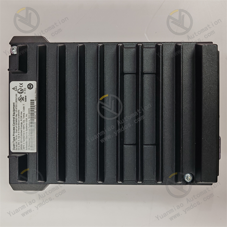
Product Type: Field Control Processor FDC280 RH101FQ.
Brand: Foxboro (a brand under Schneider Electric).
Product Code: FDC280 RH101FQ.
Memory: 16MB SDRAM, 32MB flash memory.
Input Voltage: 24V DC (typical value, redundant voltage).
Power Consumption: Maximum 8.5W per non-fault-tolerant module.
Operating Temperature: 0°C to +60°C (+32°F to +140°F).
Dimensions: 14.7cm × 5.15cm × 11.4cm.
Weight: 0.6 kg (shipping weight 1.5 kg).
Functional Features
Input Signal Processing: As a digital input module, it receives and processes digital input signals such as switch states, button states, and sensor outputs, converting these signals into data usable by automation control systems for further processing and decision-making.
Multi-Channel Design: Typically features multiple input channels to monitor and process multiple digital input signals simultaneously.
Support for Multiple Input Types: Accommodates various input types, including discrete inputs (e.g., switches, buttons) and digital signals (sensor outputs).
Data Transmission: Transmits digital input signals to control systems via specific communication protocols (e.g., Modbus).
Programmable Function: Some modules may offer programmable functionality, allowing users to configure and customize settings according to specific application requirements.
Application Areas
Hydrocarbon Processing: Used in petroleum, natural gas, and other hydrocarbon processing industries to monitor and control process parameters, ensuring safe and efficient production.
Chemical and Specialty Chemicals: Enables precise control of reaction conditions and material transportation in chemical production to guarantee product quality and production safety.
Upstream Oil and Gas: Achieves remote monitoring and automation control of equipment in oil and gas extraction and transportation to improve production efficiency and reliability.
Power Generation: Applicable to thermal, hydro, and wind power generation scenarios to monitor and control power equipment operation, ensuring stable power system performance.
Metals and Mining: Automates control of production equipment and transportation systems in metal smelting and mining to enhance efficiency and safety.
Water and Wastewater Treatment: Controls equipment and monitors processes in water and wastewater treatment plants to ensure water quality compliance and stable operations.
Pharmaceuticals and Life Sciences: Strictly controls pharmaceutical production equipment and processes to maintain consistent drug quality and stability.
General Steps for Installing and Configuring FOXBORO FDC280 RH101FQ
1. Pre-Installation Preparation
Hardware Check: Ensure the installation environment meets the FDC280’s hardware requirements, including a suitable power supply (typically 24V DC), an operating temperature range of 0 to +60°C, and sufficient space for the module (14.7cm x 5.15cm x 11.4cm).
Documentation Review: Prepare relevant product manuals, installation guides, and technical documents for reference during installation and configuration.
Tool Preparation: Gather necessary tools such as screwdrivers and wrenches.
Documentation Review: Prepare relevant product manuals, installation guides, and technical documents for reference during installation and configuration.
Tool Preparation: Gather necessary tools such as screwdrivers and wrenches.
2. Installation Steps
Mounting Location Selection: Choose an appropriate installation location based on site conditions. The FDC280 can be mounted on a DIN rail in horizontal or vertical orientation, with easy access for wiring, maintenance, and adequate heat dissipation.
Module Installation: Secure the FDC280 module to the selected DIN rail to prevent shaking or looseness. For redundant configurations, install primary and backup modules as required and make corresponding connections.
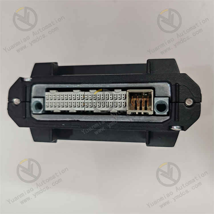
Wiring: Connect the FDC280’s power supply, input/output signals, and communication lines according to the wiring diagram. Ensure correct power polarity, connect I/O signals to corresponding field devices, and link communication lines to the control system network (e.g., Ethernet or serial interface). Pay attention to wiring specifications and quality for stable signal transmission.
Module Installation: Secure the FDC280 module to the selected DIN rail to prevent shaking or looseness. For redundant configurations, install primary and backup modules as required and make corresponding connections.
Wiring: Connect the FDC280’s power supply, input/output signals, and communication lines according to the wiring diagram. Ensure correct power polarity, connect I/O signals to corresponding field devices, and link communication lines to the control system network (e.g., Ethernet or serial interface). Pay attention to wiring specifications and quality for stable signal transmission.
3. Configuration Steps
Software Installation: Install appropriate configuration software on the control host or workstation connected to the FDC280. Typically, this requires installing control core service software for Foxboro DCS and other related packages, ensuring compatibility with the FDC280 module.
Hardware Recognition: Launch the configuration software to automatically detect the installed FDC280 module. If the module is not recognized, check hardware connections and driver installations.
Parameter Setting: Configure parameters for the FDC280 in the software based on application requirements, including definitions for I/O channels, signal types, range settings, and communication protocols. For example, set corresponding channels as discrete input types if connected to switch signals, and configure Modbus parameters (baud rate, data bits, stop bits) for Modbus communication.
Control Logic Configuration: Write or import control logic programs into the FDC280 via the configuration software based on process flows and control requirements. Logic can range from simple switch control to complex regulatory or sequential control (e.g., programming a logic to drive field equipment when a specific input signal is met).
Download and Activation: After completing parameter settings and logic configuration, download the configured file to the FDC280 module and activate the configuration for operational use.
How to Troubleshoot FOXBORO FDC280 RH101FQ
I. Preliminary Checks: Basic Status Verification
- Power and Hardware Connections
- Check signal cables (e.g., 4-20mA, HART, PROFIBUS) for looseness, short circuits, or poor grounding.
- Ensure pneumatic/hydraulic (if applicable) are securely connected without leaks.
- Power Supply Check: Confirm normal power input (voltage and frequency within specifications) and that the power indicator is on. If not, inspect power cables, fuses, or the power supply circuit.
- Cable Connections:
- Hardware Appearance: Inspect the device casing for physical damage, overheating marks, or water ingress.
- System Communication Test
- Protocol Verification: Ensure the device’s configured communication protocol (e.g., HART, Modbus) matches the control system, with consistent parameters (baud rate, address, etc.).
Data Interaction Test:
- Use specialized tools (e.g., FOXBORO’s PACTware or third-party software) to connect to the device and read real-time data or send control commands.
- If communication fails, check for faulty communication modules, damaged cables, or try replacing ports/cables.
II. Common Fault Types and Solutions
- Unresponsive Device or Communication Interruption
- Possible Causes: Power failure, incorrect communication parameters, faulty communication module, or cable issues.
Troubleshooting Steps:
- Reconnect power and communication cables, then reboot the device.
- Check for address conflicts with other network devices (e.g., unique Modbus slave addresses).
- Replace the communication module or test with a backup port (if redundant).
- Use a multimeter to measure communication line resistance and signal voltage to identify damaged cables or interference (keep away from electromagnetic sources).
- Invalid Control Commands or Abnormal Execution
- Possible Causes: Incorrect control parameter settings, mechanical jamming of actuators, air/hydraulic supply faults, or abnormal sensor feedback.
Troubleshooting Steps:
- Ensure the device is in "remote control" mode (not locally locked) and receives commands within valid ranges (e.g., 4-20mA corresponding to 0-100% stroke).
- Manually operate the device (e.g., local knob) to observe actuator movement:
- Check air/hydraulic pressure and for leaks.
- Compare sensor feedback values with command values (e.g., valve position feedback). Large deviations may indicate sensor failure or calibration issues; recalibrate or replace sensors.
- If manual operation works, check for control system command errors or communication link issues.
- If manual operation is jammed, inspect mechanical components (e.g., valve stems, linkages) for blockages, insufficient lubrication, or wear; clean or replace parts as needed.
- Alarm or Fault Code Indications
- Common Alarm Types:
- Clear alarms and monitor for recurrence. Persistent alarms may indicate hardware failures (e.g., damaged circuit boards or motor drives), requiring factory repair or replacement.
- Overheating: Check for blocked vents, excessive ambient temperature, or faulty fans.
- Sensor Faults: Inspect sensor wiring or replace faulty sensors (e.g., level, pressure sensors).
- Stroke Limit Exceeded: Verify limit switches or control logic if the actuator reaches its limit without a stop signal.
Steps:
- Review alarm codes (e.g., "E01," "FAULT 4") on the device display or control system and refer to the manual for explanations.
- Data Fluctuations or Accuracy Issues
- Possible Causes: Signal interference, degraded sensor accuracy, mechanical vibration, or improper parameter settings (e.g., too small filter time constant).
Troubleshooting Steps:
- Route signal cables separately from power cables to avoid EMI (use shielded cables with proper grounding).
- Calibrate sensors (zero and span) and verify accuracy with standard equipment.
- Adjust device parameters (e.g., increase filter time, set deadband) to reduce environmental noise.
- Check mechanical installations for looseness due to vibration (e.g., terminal blocks, sensor mounts).

III. Advanced Troubleshooting: System-Level and Software Aspects
- Control System Compatibility Issues
- Ensure device firmware and control system software versions are compatible; update firmware or drivers as needed.
- Verify correct configuration (e.g., device type, I/O signal types, unit conversion parameters).
- Logic Program and Interlock Testing
- If device interlocks with other systems (e.g., PLC, DCS) fail, check for control logic conflicts (e.g., interlock protections, priority settings).
- Use simulation tools or step-by-step testing to validate signal paths and logic responses against design requirements.
- Redundant System Faults
- For redundant configurations (e.g., dual power supplies, communication modules), switch to backup modules to test primary module functionality.
- Ensure redundant switching mechanisms operate correctly to prevent delays or misoperations.
IV. Maintenance Recommendations and Preventive Measures
- Regular Calibration: Calibrate device accuracy periodically (e.g., annually) to maintain measurement and control precision.
- Environmental Management: Keep the installation environment clean and dry; regularly remove dust to prevent moisture or corrosive gas damage.
- Spare Parts Management: Stock common spares (e.g., communication modules, sensors, fuses) for quick replacement.
- Record-Keeping and Analysis: Maintain a fault log to document alarm times, codes, and solutions; analyze recurring issues for preventive maintenance.
Note: Always follow safety procedures in high-pressure, high-temperature, or hazardous environments, and consult FOXBORO technical support or certified personnel for unresolved issues.