Module")
 Module")
 Module")
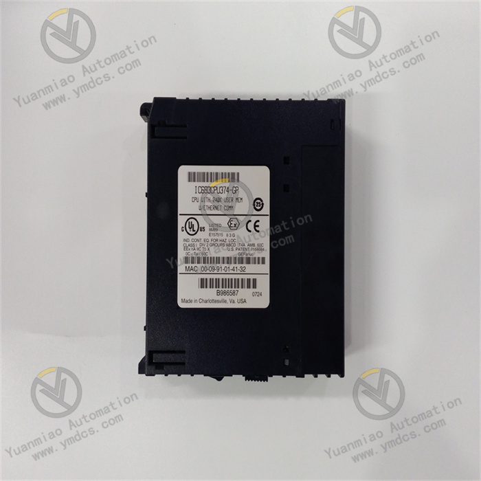
Description
I. Performance Characteristics
1. High-Performance Processing
- Equipped with a 32-bit RISC processor running at 50 MHz, supporting high-speed data processing and complex logic operations. Ideal for medium to large-scale automation control systems.
- Built-in 64 KB program memory and 64 KB data memory (expandable to 256 KB) to meet storage requirements for complex control programs.
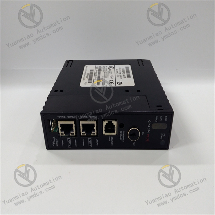
2. Rich Communication Capabilities
- Supports industrial communication protocols such as Modbus RTU and Genius Bus, enabling seamless communication with GE Fanuc I/O modules, HMIs, and third-party devices.
- Features RS-232/RS-485 communication ports for point-to-point or network communication (e.g., building distributed control systems via Genius Bus).
3. Flexible Expandability
- Compatible with GE Fanuc Series 90-30 I/O modules, supporting up to 7 I/O racks (connected via expansion cables) and expandable to 256 I/O points.
- Supports expansion with intelligent modules (e.g., high-speed counter modules, PID control modules, communication modules) to meet diverse control requirements.
4. Reliable Industrial-Grade Design
- Operating Temperature Range: 0°C to 60°C, suitable for industrial environments with temperature fluctuations.
- Vibration/shock resistance complies with IEC 60068-2-6/2-27 standards, ideal for harsh industrial settings (e.g., factory workshops, production lines).
- Built-in watchdog timer and power failure detection, with non-volatile memory (battery-backed) to ensure program and data integrity during power outages.
5. Ease of Programming and Debugging
- Supports multiple programming languages including Ladder Diagram (LD), Instruction List (IL), and Function Block Diagram (FBD), compatible with Proficy Machine Edition software for user-friendly operation.
- Features online programming, real-time monitoring, and fault diagnosis capabilities for quick identification of program errors or hardware anomalies.
II. Technical Parameters
| Parameter Category | Details |
|---|---|
| Processor Type | 32-bit RISC processor, 50 MHz clock speed |
| Memory | - Program Memory: 64 KB (expandable to 256 KB) - Data Memory: 64 KB (battery-backed) |
| Communication Interfaces | - 1 RS-232 port (programming/debugging) - 1 RS-485 port (Genius Bus communication) |
| I/O Expansion | Supports 7 I/O racks, up to 256 I/O points maximum |
| Power Supply | - Input Voltage: 9-32 VDC (DC power) - Power Consumption: ≤ 5 W |
| Physical Dimensions | 101.6 mm (H) × 50.8 mm (W) × 127 mm (D) |
| Protection Class | IP20 (requires installation in control cabinet) |
III. Working Principle
1. Program Execution Flow
- Scan Cycle: Adopts a cyclic scanning mechanism, sequentially executing input sampling, program execution, and output refresh phases to ensure real-time control logic.
- Input Sampling: Reads input signals from field sensors, buttons, etc., via I/O modules and stores them in input image registers.
- Program Execution: Processes input signals based on ladder logic or instruction lists, updating internal registers and output image registers.
- Output Refresh: Drives actuators (e.g., relays, inverters) via I/O modules using results from output image registers.
2. Communication Mechanism
- Communicates with expansion I/O modules or other controllers via Genius Bus protocol for data sharing and distributed control.
- Supports master-slave mode: As a master, polls slave devices (e.g., I/O modules) for data; as a slave, responds to read/write requests from the master.
3. Fault Diagnosis and Protection
- Built-in self-diagnosis function: Monitors hardware status (processor, memory, communication ports) in real-time. Alerts via LED indicators (e.g., FAULT light) upon detecting faults (e.g., memory errors, communication interruptions).
- Supports redundancy configuration (requires redundant modules) to enhance system reliability (e.g., dual power supplies, hot-swappable dual processors).
IV. Operation Guide
1. Installation Steps
- Location: Mount vertically in a control cabinet with good ventilation, away from heat sources and strong electromagnetic interference.
- Fixing Method: Secure using DIN rail or screws to ensure stability.
- Wiring Requirements:
- Power: Connect 9-32 VDC power supply, observing correct polarity.
- Communication: Connect RS-485 port to Genius Bus using shielded twisted-pair cable. Configure termination resistors (120 Ω) based on network topology.
- I/O: Connect to I/O rack backplane via flat cable.
2. Programming and Configuration
- Software Setup: Install Proficy Machine Edition, create a new project, and select Series 90-30 CPU374.
- Program Development: Design control logic using ladder diagrams or function blocks. Define I/O variables (e.g.,
%Ifor input registers,%Qfor output registers). - Program Download: Transfer the program to the CPU via RS-232 port or Ethernet (requires communication module). Enable online mode for debugging.
3. Commissioning and Testing
- Input Test: Short input terminals and verify corresponding register state changes in programming software.
- Output Test: Force-output points via software and observe actuator responses (e.g., relay activation, indicator lights).
- Communication Test: Connect to the Genius Bus network and check data exchange between master and slave devices (e.g., monitor slave I/O data via software).
V. Common Faults and Solutions
| Fault Phenomenon | Possible Causes | Solutions |
|---|---|---|
| Power indicator not lit | - Power not connected - Faulty power cable - Damaged CPU | - Check power input voltage - Replace power cable - Contact technicians to replace CPU |
| FAULT light constantly on | - Program errors - Memory faults - Communication interruptions | - Download correct program - Check battery level (replace battery if needed) - Inspect communication cables and termination resistors |
| No response from I/O points | - Loose wiring - Faulty I/O module - Address conflicts | - Tighten wiring connections - Replace I/O module - Check for duplicate I/O address configurations |
| Communication failure | - Baud rate mismatch - Bus short circuit - Slave device faults | - Verify communication parameters (baud rate, parity) - Check bus connections - Disconnect slave devices one by one for troubleshooting |
| Program loss | - Depleted battery - Memory hardware failure | - Replace backup battery (complete within 5 minutes of power outage) - Replace CPU module |
VI. Application Scenarios
- Industrial Automation: Suitable for manufacturing production line control, process automation (e.g., chemical, power, water treatment), and mechanical equipment control.
- Distributed Control Systems (DCS): Builds small to medium-sized distributed systems via Genius Bus to achieve centralized monitoring of multiple workstations or devices.
- Motion Control: Combined with high-speed counter modules or positioning modules, it enables simple motion control (e.g., conveyor speed adjustment, servo motor positioning)