Description
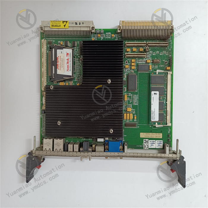
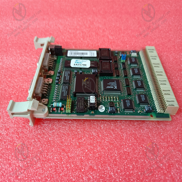
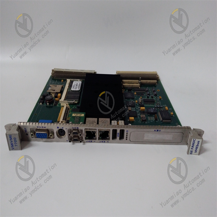
VMIVME-7700-111000
I. Overview
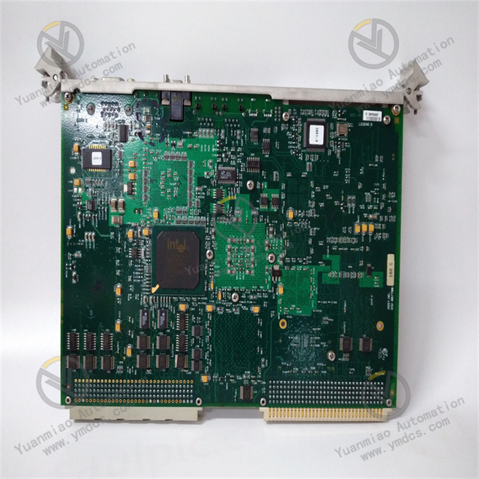
The Abaco Systems VMIVME-7700-111000 is a VMEbus Single-Board Computer (SBC) specifically designed for high-demand scenarios such as industrial control and data acquisition. With its excellent performance and reliable quality, the product has gained widespread application in multiple industries. It adopts a compact single-slot, passive-cooled Eurocard form factor, built on the mature VME (VersaModule Eurocard) bus architecture, ensuring stability and expandability during operation. This enables it to fully meet the requirements for high-performance computing and data processing in various complex environments. Although the product has entered the Restricted Production Phase (RPP), it still plays an important role in specific fields.
II. Functional Features
(1) High-Performance Processor
Equipped with an Intel x86 architecture processor, it provides the device with powerful computing capabilities. For example, in industrial automation scenarios, when facing real-time processing of massive sensor data and complex logic operations, this processor can respond quickly to ensure efficient system operation and effectively improve production efficiency. Whether it is real-time monitoring and control of equipment operation in industrial automation or rapid analysis of massive data in data acquisition scenarios, this processor can easily handle them.
(2) Sufficient Memory Configuration
Supporting up to 4GB of RAM, it provides ample space for system operation and temporary data storage. When processing large-scale data or running multiple complex applications, the sufficient memory can effectively prevent system lag or even crashes caused by insufficient memory, ensuring continuous and stable system operation. Taking medical image processing as an example, when processing high-resolution medical image data, a large amount of memory is required for temporary storage and data operation, and the large memory configuration of VMIVME-7700-111000 can well meet this need.
(3) Diverse I/O Interfaces
- VMEbus Interface: As a key interface for the device to connect to the VMEbus system, it ensures efficient and stable data transmission with other VME devices. In an industrial control network with multi-device collaboration, it can quickly and accurately interact with other devices, ensuring the real-time performance and reliability of the entire system.
- Serial Port: Facilitates connection with various devices requiring serial communication, such as some industrial sensors and intelligent instruments, enabling precise control and data acquisition of these devices in industrial automation production lines.
- Ethernet Port: Provides high-speed network connection capabilities, enabling data sharing and remote control between the device and other networked devices. In remote monitoring systems, it can quickly transmit collected data to a remote server, allowing staff to grasp the equipment operation status in real time.
- USB Port: Convenient for connecting various USB devices, such as storage devices and input devices, increasing the device's versatility and flexibility. For example, a mobile storage device can be quickly accessed via the USB interface for convenient data backup and transfer.
- Analog I/O: Capable of collecting and outputting analog signals, suitable for application scenarios requiring processing of continuously changing physical quantities, such as monitoring and adjustment of analog quantities like temperature and pressure in industrial process control.
- Digital I/O: Used for input and output of digital signals, which can be directly connected to digital circuit devices to achieve logical control of equipment in industrial automation control, such as start-stop control of motors and on-off control of valves.
(4) Extensive Operating System Support
Supports multiple operating systems, including Linux, Windows, VxWorks, etc. Users can flexibly choose suitable operating systems according to their application requirements and development habits, which greatly improves the device's applicability and expandability. For example, in industrial control scenarios with extremely high real-time requirements, users can choose the VxWorks operating system to ensure the system can quickly respond to external events; while in scenarios requiring running general software, the Windows operating system can provide better compatibility.
(5) Robust and Durable Design
- Dimensions and Form Factor: Adopts the VMEbus standard size of 233mm x 167mm x 28mm. The compact form factor allows it to adapt to various installation environments with limited space, while ensuring reasonable layout of internal components without affecting device performance.
- Operating Temperature Range: The operating temperature range is -40°C to +85°C. Even in extremely harsh industrial environments, such as high-temperature steel smelting workshops or low-temperature cold storage, it can operate stably, ensuring the device works normally under different working conditions.
- Storage Temperature Range: The storage temperature range is -55°C to +90°C, enabling it to adapt to a wide range of temperature conditions during the storage phase when the device is not in use, extending the device's service life.
- Humidity Adaptability: The humidity adaptability range is 5% to 95% RH (non-condensing). In humid environments, such as chemical production workshops or coastal operation environments, it will not fail due to humidity issues, ensuring normal device operation.
- Vibration and Shock Resistance: Capable of withstanding 5g RMS vibration from 10Hz to 500Hz and 30g half-sine pulse shocks with a duration of 11ms. In industrial fields with large vibrations and shocks, such as mining and construction, the device can still maintain stable operation, ensuring accurate data collection and processing.
III. Working Principle
(1) System Startup Process
When the VMIVME-7700-111000 is connected to the VMEbus system and powered on, the onboard power management circuit first converts, stabilizes, and filters the input power to provide stable and adaptive working voltages for internal components of the device, such as the processor, memory, and various interface circuits. Subsequently, the processor reads the startup code from storage devices (such as built-in CompactFlash or storage devices connected via the IDE interface) and loads the operating system kernel and related drivers. During this process, the BIOS comprehensively detects and configures the system's hardware resources, including memory initialization, timer setup, I/O interface initialization, etc., to ensure all parts of the device are in normal working condition, preparing for subsequent data processing and task execution. If the device is configured with a network boot function, after completing basic hardware initialization, it can obtain startup files from a remote server via the Ethernet controller according to relevant network protocols to complete system startup.
(2) Data Processing Mechanism
In the data processing process, when the system receives external data processing task instructions, the processor parses and computes the tasks according to preset programs and algorithms. Taking industrial automation control as an example, when sensors collect real-time data on equipment operation, the data is transmitted to the processor through corresponding I/O interfaces. The processor uses its powerful computing capabilities to quickly analyze this data and determine the equipment's operating status. During the operation process, the processor frequently interacts with the onboard memory, reading required data from the memory and timely storing operation results back into the memory. At the same time, with the high-speed cache mechanism inside the processor, data that may be frequently used is pre-stored in the high-speed cache to reduce data reading time and improve operation efficiency. For data requiring complex operations, such as statistical analysis of a large amount of historical data in data analysis applications, the processor can quickly handle complex logical operations and data manipulations to ensure the accuracy and timeliness of analysis results.
(3) Data Transmission Principle
- VMEbus Data Transmission: The device transmits data with external devices through the VMEbus. When communicating with other VMEbus devices, data is orderly transmitted between devices through address lines, data lines, and control lines under the specification of the VMEbus protocol. For example, in an industrial automation production line, as the main controller, VMIVME-7700-111000 needs to interact with multiple slave devices. Through the VMEbus, it can quickly and accurately send control instructions to slave devices and receive data fed back by slave devices.
- Ethernet Data Transmission: For the onboard Ethernet controller, when performing network data transmission, it follows the Ethernet protocol to encapsulate and decapsulate data. When the device needs to send locally processed data to other devices in the network, the data is first transmitted to the Ethernet controller, which encapsulates the data into Ethernet frames according to Ethernet standards and sends them to the network through the Ethernet port; when receiving data, the process is reversed—the Ethernet controller receives Ethernet frames from the network, decapsulates them, and transmits the data to the processor or memory for subsequent processing. For example, in a remote monitoring system, the device transmits collected data to a remote server via Ethernet, facilitating managers to view equipment operation status remotely.
- Data Transmission via Other Interfaces: In serial communication, data is transmitted bit by bit in bytes according to the serial communication protocol, achieving low-speed and stable communication between the device and serial devices. USB interface data transmission follows the USB protocol, capable of quickly transmitting large amounts of data, suitable for scenarios such as external storage devices and input devices. Analog I/O interfaces convert analog signals to digital signals (during collection) or digital signals to analog signals (during output) to achieve processing and control of analog quantities; digital I/O interfaces directly perform high-low level input and output operations on digital signals to achieve logical control of digital devices.
IV. Operation Guide
(1) Pre-installation Preparations
- Compatibility Check: Before installation, carefully verify the detailed specifications of the target VMEbus system. Focus on key information such as the type, quantity, electrical characteristics, and available power of VMEbus slots to ensure full compatibility with the VMIVME-7700-111000. Incompatible systems may lead to installation failure or even device damage, so compatibility confirmation is a crucial step before installation.
- Tool Preparation: Prepare necessary installation tools, such as anti-static wristbands and screwdrivers of suitable sizes. During operation, be sure to wear an anti-static wristband to prevent static electricity generated by the human body from damaging sensitive electronic components inside the device, ensuring the safety of the installation process.
- Environmental Check: Check whether the temperature, humidity, vibration, and other conditions of the device installation environment meet the device's working requirements. Avoid installing the device in environments with excessively high or low temperatures, excessive humidity, or severe vibration to ensure normal device operation.
(2) Module Installation
- Chassis Opening Operation: Carefully open the VMEbus system chassis and find a suitable 6U single-slot position inside to prepare for installing the VMIVME-7700-111000 module.
- Module Insertion Steps: Hold the VMIVME-7700-111000 module, precisely align the interface at the bottom of the module with the VMEbus slot, maintain the module in a vertical state, and insert the module into the slot smoothly and slowly. During insertion, pay attention to moderate force to avoid bending or damaging the interface pins until the module is fully inserted into the slot and fixed firmly.
- Module Fixing Key Points: Use a screwdriver to tighten the fixing screws on both sides of the module one by one to ensure the module is firmly installed in the chassis without shaking, providing a solid physical guarantee for the stable operation of the device.
(3) Device Connection
- Storage Device Connection (Optional): To connect storage devices such as IDE drives, prepare corresponding data cables and power cables. Connect one end of the data cable to the device's IDE interface and the other end to the storage device's interface; at the same time, correctly connect the power cable to the storage device to provide power, enabling data storage and reading between the device and the storage device. If the device is equipped with a CompactFlash card, it can be directly inserted into the corresponding card slot.
- Network Device Connection: Connect the device's Ethernet port to a network switch or other network devices with Ethernet cables, and configure the device's network parameters such as IP address, subnet mask, gateway, etc., according to the actual network environment to ensure the device can normally access the network and achieve network data transmission and sharing.
- Other Device Connections: Connect required serial devices, USB devices, analog I/O devices, digital I/O devices, etc., through corresponding interfaces according to actual application requirements. When connecting, pay attention to the type and direction of the interface to ensure correct connection. For example, when connecting a serial device, pay attention to the setting of serial communication parameters such as baud rate, data bits, stop bits, etc., which need to be consistent with the device's parameters.
(4) System Startup and Operation
- System Startup Process: After completing all device connections, close the VMEbus system chassis and turn on the system power. The device will start up. During this process, pay attention to observing the status of the device's indicator lights. Under normal circumstances, the indicator lights will turn on or flash in a specific order, indicating that the device is performing self-checking and other startup processes. If the indicator lights display abnormally, refer to the device manual or contact technical support personnel for troubleshooting.
- System Login and Operation: After the device starts up, enter the correct username and password in the corresponding login interface according to the installed operating system for login. After successful login, you can use the device's various functions for data processing, control operations, etc., through the operating system or related application programs. For example, in industrial automation applications, you can remotely monitor and control production equipment through corresponding control software; in data acquisition applications, you can start a data acquisition program to collect and analyze sensor data in real time.
(5) Common Fault Troubleshooting
- Device Fails to Start: Check whether the power connection is stable and confirm whether the external power supply is normal; check the status of the device's indicator lights. If the indicator lights do not light up or display abnormally, the internal power module of the device may be faulty, and professional technical personnel need to be contacted for maintenance. At the same time, check whether the startup device (such as the storage device, network startup configuration) is normally connected and has complete data. If the startup device has problems, it may cause the system to fail to start normally.
- Abnormal Network Connection: If the device cannot connect to the network normally, check whether the Ethernet cable is damaged, and try to re-plug or replace the cable; confirm whether the network parameter configuration is correct, and test network connectivity by using commands such as ping. If the problem still persists, check whether the Ethernet controller driver is correctly installed and is the latest version, which can be downloaded and updated from the device manufacturer's official website.
- I/O Interface Failure: If a certain I/O interface cannot work normally, check whether the interface connection is loose and whether the device connection is correct. For serial communication failures, check whether the serial communication parameter settings are correct; for analog I/O and digital I/O interface failures, the interface can be tested through test software to determine whether it is a hardware failure or a software configuration problem. In case of hardware failure, contact technical support personnel for maintenance or replacement of relevant components.