Description
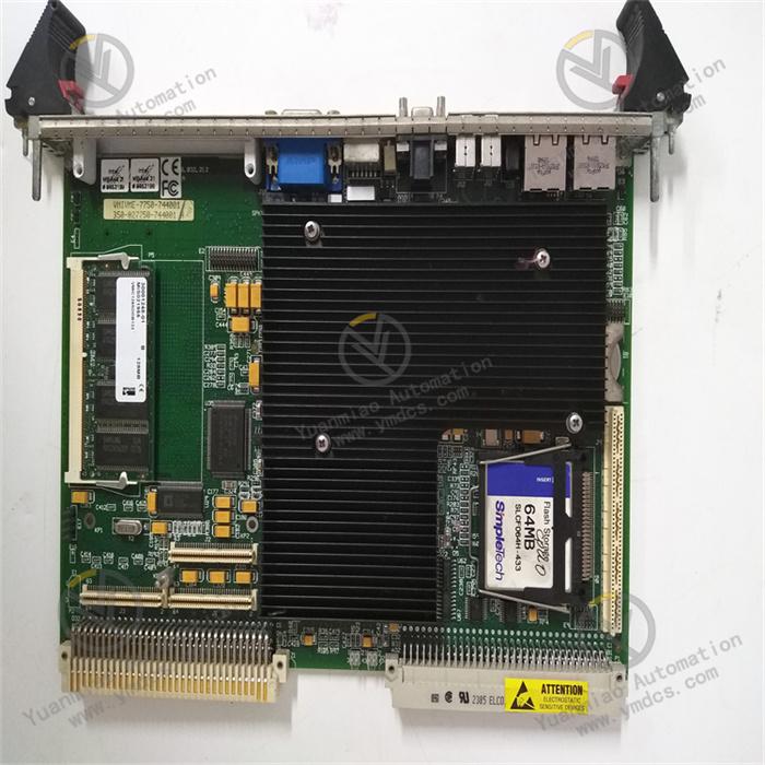
VMIVME-7750-744001/350-027750-744001 H
Overview
The Abaco Systems VMIVME-7750-744001/350-027750-744001 H is a high-performance VMEbus Single-Board Computer (SBC) that entered the Restricted Production Phase (RPP) on February 5, 2009. Based on the mature VME (VersaModule Eurocard) bus architecture—widely used in industrial control, data acquisition, and other fields for its high performance, reliability, and customizability—the device features a rugged single-slot design with passive cooling, ensuring reliable operation in harsh industrial environments. Integrated with an Intel Pentium III processor and advanced chipset technology, it delivers powerful processing capabilities for complex tasks. Its rich memory options, diverse I/O interfaces, and flexible expansion capabilities make it an ideal choice for industrial automation, data acquisition systems, image processing, and other applications.
Functional Features
(1) Powerful Processing Performance
Equipped with an Intel Pentium III processor up to 1.26GHz, adopting the advanced x86 architecture with 32-bit addressing and a 64-bit data bus. Its superscalar architecture, combined with dynamic branch prediction technology, accurately predicts program execution paths, effectively reducing instruction execution latency. Independent instruction and data caches accelerate data reading and storage, and with MMX technology, it can execute three instructions per clock cycle, excelling in multitasking and complex algorithm operations. It efficiently processes real-time data, fully meeting the rigorous requirements of industrial automation, data acquisition, and other fields for high-speed data processing.
(2) Flexible and Efficient Memory Configuration
Supports up to 512MB of PC133 SDRAM, expandable via a 144-pin SODIMM slot, allowing users to flexibly adjust memory capacity according to actual application needs. The memory uses dual-port DRAM connected to the VMEbus, significantly improving data transfer efficiency during multi-device communication and ensuring the system maintains smooth and stable operation when running memory-intensive applications, without performance bottlenecks.
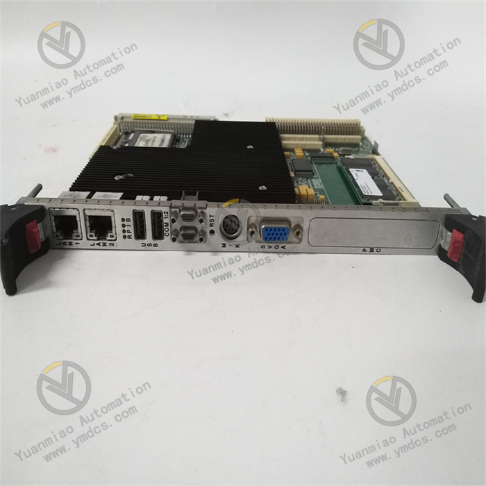
(3) Diverse I/O Interfaces
- VMEbus Interface: Strictly compliant with VMEbus Rev. C.1 standard, enabling high-speed data exchange for multi-processor systems. It can function as a master device to initiate data transmission actively or as a slave device to respond to other devices' requests. Through transparent PCI-VME bridging technology, it collaborates with other VME devices to ensure seamless data transmission across the VMEbus ecosystem, providing a solid foundation for complex industrial control systems.
- Ethernet Interface: Onboard Ethernet interface supports high-speed network connections to meet data interaction needs with external networks. It also enables remote boot via relevant protocols, facilitating remote system deployment and management—especially suitable for distributed industrial control systems and remote data acquisition scenarios, allowing engineers to complete device boot and basic configuration without on-site presence.
- Storage Interface: Features an IDE interface for convenient connection of local storage devices (e.g., hard drives) to store system files, applications, and large data volumes. Some models also support CompactFlash storage, which offers advantages like small size and strong shock resistance, suitable for applications requiring space and stability.
- Expansion Interface: Equipped with a PCI-X 66MHz PMC expansion slot, allowing users to insert various custom I/O modules (e.g., serial, USB, analog/digital I/O) based on specific application scenarios, greatly expanding device functions. This enables flexible adaptation to different needs, whether adding extra communication interfaces or performing special data acquisition and control via PMC modules.
(4) Wide Operating System Compatibility
Supports multiple real-time and general-purpose operating systems, including VxWorks, Linux, and Windows. This broad compatibility allows flexible deployment in various application environments—from industrial control scenarios requiring millisecond-level real-time response to general computing scenarios needing rich software ecosystem support—enabling users to find suitable OS Adaptation,reducing development and usage costs.
Technical Parameters
| Category | Detailed Specifications |
|---|---|
| Processor | Intel Pentium III, up to 1.26GHz with 512KB L2 cache |
| Memory | Up to 512MB PC133 SDRAM |
| Storage | IDE interface; some models support CompactFlash storage |
| Network | Onboard Ethernet interface, supports remote boot |
| Expansion | One PCI-X 66MHz PMC expansion slot |
| Power Supply | +5V DC input, passive cooling design, low power consumption |
| Environmental | Operating temperature: Set per industrial standards (typically a wide range for harsh environments); Storage temperature: Meets industrial storage requirements; Humidity: Complies with industrial environmental humidity standards (non-condensing) |
Working Principle
(1) System Boot Process
When powered on, the onboard power management circuit stabilizes the input +5V DC voltage to ensure pure and stable power supply for all components. The processor then loads the BIOS program from reprogrammable flash memory, which comprehensively initializes hardware, including memory self-test, timer setup, and I/O interface configuration. After initialization, the system reads and loads the OS image from a local IDE storage device according to the preset boot order; if remote boot is configured, it can also obtain boot information from a remote server via the Ethernet interface following relevant protocols, entering normal operation.
(2) Data Processing Flow
During operation, the Pentium III processor parses tasks based on pre-programmed algorithms. When processing real-time data in industrial applications (e.g., sensor-collected data), the processor frequently reads/writes data with SDRAM, retrieving data from memory for computation and writing results back. For graphics-related tasks, the AGP graphics adapter fetches relevant data from memory, processes it, and generates high-quality visual outputs to meet operators' real-time data visualization needs. The VMEbus coordinates data transfer between the processor and external devices, ensuring accurate data flow across different devices. The Ethernet interface enables data interaction with other network devices via protocol encapsulation/decapsulation, integrating the device into the network for data sharing and collaboration.
(3) Bus Architecture Principle
Through transparent PCI-VME bridging technology, the device can act as a system controller or peripheral CPU in multi-processor systems. This bridging technology ingeniously resolves communication differences between PCI and VME buses, allowing seamless integration into the VMEbus ecosystem. In complex multi-device collaborative environments, it ensures efficient and accurate data exchange, maintaining overall system stability without data loss or failures due to bus communication issues.
Operation Guide
(1) Pre-installation Preparations
- Compatibility Check: Carefully verify VMEbus slot specifications, including electrical parameters (voltage, current, etc.) and power supply capacity, to ensure full compatibility with the VMIVME-7750-744001/350-027750-744001 H. Differences in VME slot models may cause operational failures or device damage if mismatched.
- Tools and ESD Protection: Prepare anti-static wristbands, suitable screwdrivers, and other installation tools. During installation, static electricity from the human body may cause irreversible damage to precision electronic components, so always wear an anti-static wristband and ensure the installation environment has good ESD protection (e.g., anti-static workbench mats).
(2) Module Installation Steps
- Open the VME chassis and locate an empty slot suitable for 6U device installation.
- Precisely align the device's VME interface with the slot, ensuring all pins match the slot's positions, then insert it vertically and smoothly with even force to avoid skew or poor contact. If insertion is difficult, do not force it—check the cause and retry.
- Secure the device to the slot with matching screws, tightening them to prevent loosening due to vibration, which could affect normal operation and data transmission stability.
- Connect power cables correctly and firmly per application needs to avoid power supply issues from loose connections. If using an IDE storage device, connect the corresponding cable; for functional expansion, connect PMC modules and other accessories, paying attention to interface orientation and sequence as per the manual.
(3) System Configuration Methods
- Storage and Network Setup: If using local storage, configure the IDE drive in the system (e.g., set boot order, partitions) to ensure proper recognition. For remote boot, set parameters (IP address, subnet mask, gateway, etc.) via the Ethernet interface. Correct parameter configuration is key to network connectivity and boot information acquisition, testable via the ping command.
- OS and Driver Installation: Select a suitable OS (e.g., VxWorks, Linux) based on application scenarios and install it following the steps. Pay attention to selecting correct hardware drivers, especially for PMC modules—incorrect installation may disable device functions. Refer to Abaco Systems' official documentation for a smooth installation.
(4) Common Fault Troubleshooting
- Boot Failure: First, check power connections and ensure the power indicator is on. Verify flash memory integrity for data corruption/loss using specialized tools. Check BIOS boot order settings and adjust them if incorrect to ensure booting from the right device.
- Network Issues: Check Ethernet cable connections for looseness, damage, or breakage. Update network drivers, as outdated or corrupted drivers may cause connection failures. Test network device connectivity via ping and verify TCP/IP parameter configurations, re-setting them if incorrect.
- I/O Failures: Check PMC module installation for firm seating and re-plug it to ensure reliable connection. Update PMC module firmware/drivers if necessary, as old versions may have compatibility issues. For unresolved faults, replace faulty components, ensuring compatibility and following correct procedures. Refer to Abaco Systems' official technical documentation or contact customer service for support during troubleshooting.