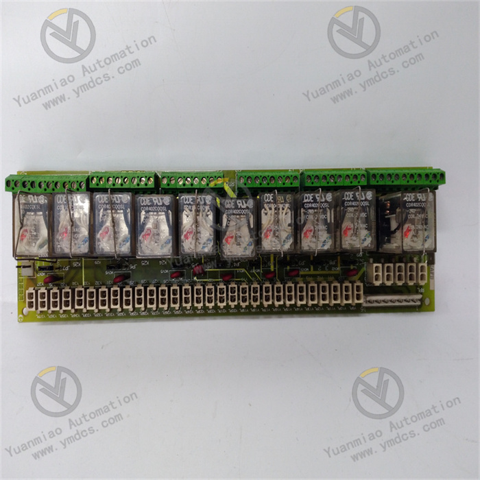
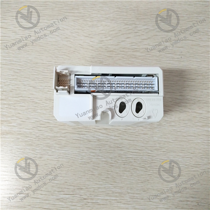
Description
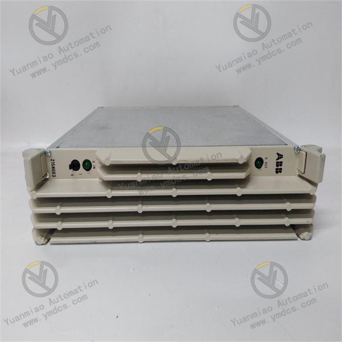
ABB DI802 3BSE022360R1
I. Overview
ABB DI802 3BSE022360R1 is a digital input module, whose core function is to collect, electrically isolate and reliably transmit field digital signals (such as equipment switch status, limit switch signals, button trigger signals, etc.). Adopting ABB's industrial-grade standardized design concept, this product integrates advanced signal processing and anti-interference technologies, and can be seamlessly integrated into the ABB AC800M PLC system architecture. It provides core support for the control system to accurately acquire the operating status of field devices and ensure the efficient execution of control logic.
Originating in Switzerland, this digital input module has strong adaptability to harsh environments and can operate stably for a long time in complex industrial scenarios such as high and low temperatures, high humidity, strong electromagnetic interference, and vibration impact. It is widely used in fields with high requirements for signal acquisition reliability and stability, including industrial automation production lines, power and metallurgical equipment control, petrochemical process management, municipal water treatment systems, and large-scale intelligent manufacturing equipment. It serves as a key signal hub connecting field digital sensors/actuators and PLC master control units. At present, there are mature supply channels in the market, which can fully meet the accessory supporting needs of industrial equipment maintenance and replacement, system upgrade and transformation, and new construction projects.

II. Product Features
High-precision Signal Acquisition and Fast Response: Adopting optimized optoelectronic isolation and signal shaping circuit design, it can accurately collect multi-channel parallel digital signals and effectively suppress the impacts of signal jitter, electromagnetic interference and voltage fluctuation. With fast signal response speed, the delay is ≤1ms in standard response mode, and the high-speed response mode can be flexibly configured. It ensures that the PLC system can capture the status changes of field devices in real time and guarantees the immediacy and accuracy of control commands.
High-reliability Industrial-grade Design: Strictly complying with ABB's design standards for industrial automation components, it selects high-grade industrial-grade components and undergoes multiple rounds of rigorous environmental stress screening and reliability verification, including high and low temperature cycles, vibration impact, and electromagnetic compatibility tests. It has excellent anti-electromagnetic interference capability, can resist the electromagnetic radiation generated by equipment such as frequency converters and high-power motors in industrial sites, and greatly reduces the failure rate under complex working conditions.
Comprehensive Isolation and Protection Mechanism: Built-in optoelectronic isolation circuits between channels with an isolation voltage of up to 2500V AC (for 1 minute continuously), which effectively avoids signal crosstalk between channels and damage to the module and PLC master control unit caused by ground potential difference. It integrates signal overvoltage protection, short-circuit protection and reverse connection protection functions, which can monitor the status of input signals in real time. When abnormal voltage or short-circuit faults are detected, it will automatically isolate the faulty channels to prevent the expansion of faults and ensure the overall operation safety of the system.
Excellent System Compatibility: Adopting standardized rack mounting dimensions and interface design, it perfectly matches the ABB AC800M series PLC systems and supports fast networking with other I/O modules and master control units in the system. It is compatible with ABB standard communication protocols, enabling high-speed data interaction with the master control unit, and also supports compatible docking with third-party systems. It has flexible system integration capability, simplifying the process of accessory replacement and system expansion.
- Convenient Operation, Maintenance and Installation Experience: Adopting modular plug-and-play design, the installation process is simple and efficient, and it can be put into use quickly without complex on-site debugging. The module interface marking is clear and standardized, and each input channel is equipped with an independent status indicator light. Operation and maintenance personnel can intuitively monitor the signal acquisition status of each channel, quickly locate faulty channels, greatly shorten maintenance downtime, and improve operation and maintenance efficiency.
III. Technical Parameters
1. Core Basic Parameters
- Product Model: DI802 3BSE022360R1
- Product Series: ABB AC800M PLC Supporting I/O Module Series
- Product Type: Industrial-grade Digital Input Module
- Manufacturer: ABB (ASEA Brown Boveri)
- Place of Origin: Switzerland
- Mounting Method: Standard Rack Mounting (compatible with ABB AC800M system standard racks)
- Core Functions: Digital Signal Acquisition, Electrical Isolation, Signal Shaping, Fault Alarm, Status Feedback
- Application Scenarios: Industrial automation production lines, power and metallurgical equipment control, petrochemical process management, municipal water treatment systems, large-scale intelligent manufacturing equipment, etc.
2. Electrical Performance Parameters
- Working Power Supply: 24V DC (wide voltage input range, compatible with 20-28V DC, suitable for industrial standard power supply environment)
- Number of Input Channels: 16-channel digital input (independent channel design, supporting simultaneous parallel acquisition of 16-channel signals)
- Input Signal Type: Universal for dry contacts/wet contacts, supporting PNP/NPN two-polarity input, compatible with different types of field sensors
- Input Voltage Range: 18-30V DC for wet contact input; dry contact input resistance ≤100Ω
- Signal Response Time: ≤1ms in standard mode, ≤0.1ms in high-speed mode (flexibly configurable via PLC configuration software)
- Isolation Method: Optoelectronic isolation between channels, electrical isolation between channels and power supply; isolation voltage ≥2500V AC (for 1 minute continuously)
- Insulation Resistance: ≥100MΩ (test voltage 500V DC)
- Withstand Voltage Performance: 1kV AC, no breakdown or flashover phenomenon for 1 minute continuously
- Power Consumption: Typical value ≤4W in no-load state, maximum value ≤7W in full-channel working state
3. Environmental and Physical Parameters
- Operating Temperature: -25℃ to +70℃ (wide-temperature design, suitable for extreme industrial environments such as severe cold and high temperature)
- Storage Temperature: -40℃ to +85℃
- Relative Humidity: 5% to 95% (no condensation, suitable for high-humidity industrial scenarios such as papermaking and water treatment workshops)
- Protection Class: IP20 (module body, suitable for installation in control cabinets, with dust-proof and solid foreign object intrusion prevention capabilities)
- Electromagnetic Compatibility: Compliant with EN 55022/EN 55024 industrial electromagnetic compatibility standards, with both radiation emission and immunity meeting industrial-grade requirements
- Vibration Resistance: 10-150Hz, acceleration 5g, no performance degradation for 30 minutes in each of the three axial directions
- Shock Resistance: 50g, 11ms, no mechanical damage or performance failure for 10 times in each of the three axial directions
- Module Dimensions: Standard rack mounting dimensions (44mm width × 100mm height × 175mm depth, subject to the actual product)
- Weight: Approximately 0.45-0.7kg (subject to the actual product)
IV. Working Principle
The core working principle of the ABB DI802 3BSE022360R1 digital input module is a closed-loop signal processing process of "signal acquisition - isolation and conditioning - logic conversion - data transmission - status feedback". Through the collaborative work of multiple internal functional units, it realizes the safe, accurate and efficient transmission of field digital signals to the PLC master control unit. The specific working process can be divided into five core stages:
Stage 1: Power Input and Protection StageExternal industrial 24V DC power supply (compatible with 20-28V DC wide voltage) is connected to the module through a standardized power interface. The built-in power protection circuit of the module starts working immediately, providing overvoltage, overcurrent and reverse connection protection for the input power supply. At the same time, it filters out clutter and high-frequency interference signals in the power supply, outputs stable and pure supply voltage, provides safety guarantee for the normal operation of each functional unit inside the module, and avoids damage to subsequent circuits caused by abnormal power supply.
Stage 2: Field Signal Acquisition StageThe module collects various field digital signals in real time through 16 independent input channels, including dry contact signals (such as the on-off status of mechanical limit switches and manual buttons) and wet contact signals (such as high and low level signals output by photoelectric sensors and proximity switches). The filter circuit at the front end of the input channel performs preliminary processing on the collected signals, filters out high-frequency noise and interference pulses in the signals, and provides a clean and stable signal source for subsequent signal conditioning.
Stage 3: Isolation, Conditioning and Logic Conversion StageThe preliminarily filtered signals enter the optoelectronic isolation unit, which realizes electrical isolation between the input signals and the module's internal circuits through high-performance optocouplers, completely eliminating the impact of strong field electromagnetic interference and ground potential difference on the module's core circuits and the PLC master control unit. The isolated signals enter the signal shaping and conditioning circuit, and after waveform restoration and level calibration, they are converted into standard digital logic signals (0/1) recognizable by the PLC master control unit, ensuring the stability and consistency of the signals.
Stage 4: Data Buffering and Communication Transmission StageThe converted standard logic signals are temporarily stored in the high-speed data buffer area inside the module to avoid data loss. The module establishes a stable communication link with the ABB AC800M PLC master control unit through a dedicated communication interface, follows the ABB standard communication protocol, and uploads the signal status data of 16 channels to the master control unit in batches at high speed. At the same time, it receives configuration commands issued by the master control unit (such as response time adjustment, channel enable/disable, fault diagnosis, etc.) to complete the dynamic configuration of the module's working parameters.
V. Common Fault Troubleshooting
1. No Signal Acquisition by Channel/Status Indicator Light Not On
2. Abnormal Signal Acquisition/Frequent Mis-triggering by Channel
3. Module Fails to Communicate with PLC Master Control Unit
4. Module Overheating/Simultaneous Failure of Multiple Channels
VI. Notes
Before installing, wiring, maintaining the module, all input power supplies and signal lines must be disconnected, and the module must be allowed to cool down completely (at least 5 minutes) to avoid the risk of high-voltage electric shock or signal short circuit; it is strictly prohibited to plug/unplug the module or adjust the wiring when it is powered on to prevent damage to the module's internal circuits, PLC master control unit and field equipment.
During installation, ensure that the module is completely fixed to the rack and tighten all mounting screws to prevent the module from loosening due to vibration; sufficient heat dissipation space must be reserved around the module (it is recommended to reserve at least 10cm on both sides and 15cm on the top), avoid installing it close to high-power heat-generating equipment, and install anti-vibration fixing devices in scenarios with large vibrations (such as metallurgical workshops and heavy machinery).
During wiring, strictly distinguish between power interfaces, signal input interfaces and communication interfaces, and wire according to the module interface marking specifications; shielded cables should be preferred for signal lines, with the shielded layer reliably grounded at one end; power lines, signal lines and communication lines should be wired separately with a spacing of not less than 30cm, and kept away from strong electromagnetic interference sources to reduce interference between lines.
During the operation of the module, it is necessary to regularly monitor key parameters such as the module's working voltage, channel signal status and module surface temperature to ensure that all parameters are within the normal range; conduct a comprehensive inspection of the module interfaces and wiring connectors every 3-6 months, clean dust, fasten loose connectors, and replace aging and damaged lines in a timely manner; regularly verify the module parameters through PLC configuration software to ensure consistency with the system configuration.
When replacing the module, ABB genuine DI802 3BSE022360R1 modules must be used, and it is strictly prohibited to use alternative products with inconsistent models, mismatched specifications or poor quality; after replacement, re-verify the correctness of wiring and communication parameter settings, test the signal acquisition function of each channel one by one, and only put it into formal operation after confirming that the module is working normally.
- When the module is idle for a long time, it should be stored in an environment with a temperature of -40℃ to +85℃, dry and ventilated, free of corrosive gases and strong vibration to avoid performance degradation of the module caused by moisture, high temperature, collision or chemical corrosion; before storage, all wiring should be removed, and the interfaces should be sealed and protected to prevent dust from entering the module interior.