Description
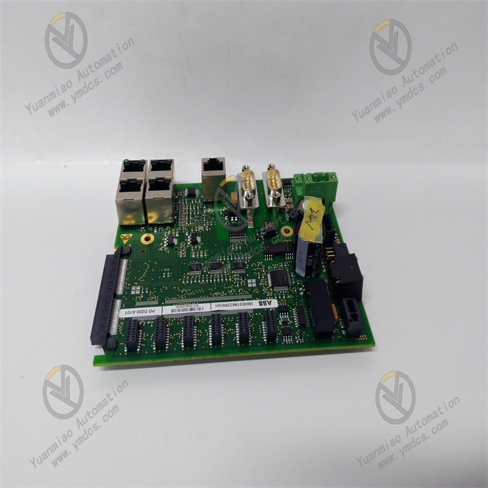
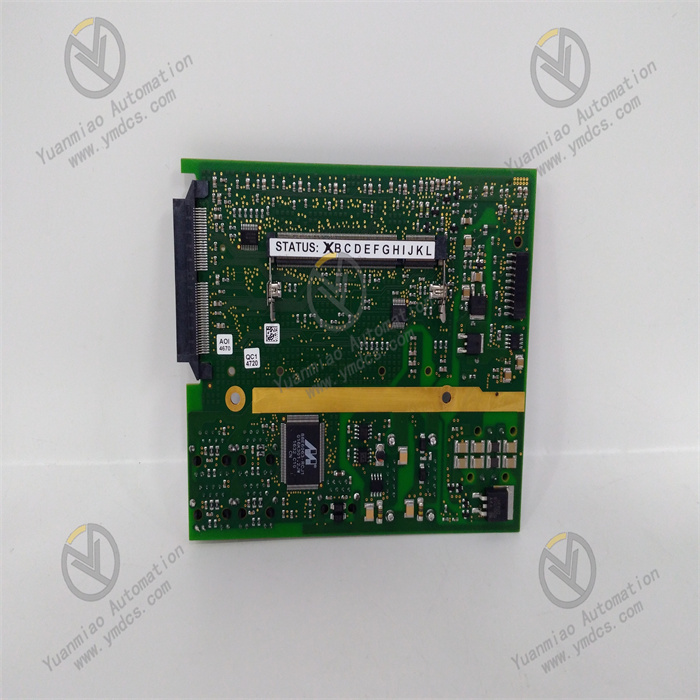
ABB PDD200A101 3BHE019633R0101
1. Product Description
Model: PDD200A101
- Version: Standard Edition
- Global Part Number: 3BHE019633R0101
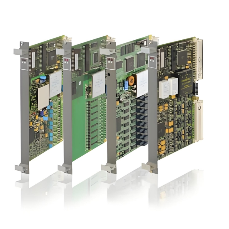
- Product Series: ABB AC 800M Industrial Control Module Series
- Product Category: Industrial Control Circuit Board / Composite Module for Digital I/O and Excitation Control
Country of Origin: Sweden
Core Functions
It supports Modbus RTU and ABB proprietary industrial protocols, enabling seamless integration with AC 800M controllers and CI854 communication modules for rapid deployment without additional drivers. Equipped with a front-mounted LED diagnostic array and self-diagnostic function, it monitors channel status, communication links, and power supply health in real time. It supports three-level user rights management (Administrator / Operator / Read-only) and generates detailed operation and fault logs for traceability and troubleshooting. Signal response speed is optimized (input ≤ 1ms, output ≤ 10ms). Dual redundant 24VDC power input (±10%) ensures strong immunity to harsh industrial electromagnetic interference, resolving occasional channel failures and communication lag issues in earlier versions, and guaranteeing real-time performance and stability of control and excitation regulation.
Application Scenarios

2. Specifications
| Parameter Category | Details |
|---|---|
| Software Specifications | Supported Protocols: Modbus RTU, ABB AC 800M proprietary protocol, IEC 60870-5Communication Functions: 16 digital inputs + 8 outputs; input response ≤ 1ms, output response ≤ 10ms; adjustable filtering 0.1–20msAccess Control: Three-level permissions (Administrator / Operator / Read-only)Logging: Supports export of communication, fault and operation recordsCompatibility: Seamless with AC 800M controllers, CI854/CI871 communication modules; compatible with Windows Server 2012 R2 or later; supports ABB Control Builder M programming toolsDiagnostics: Alarms for channel failure, power abnormality, communication interruption; fault location via LED indicators |
| Hardware Requirements | Recommended Control Station: CPU ≥ Intel Core i3, RAM ≥ 4GB (8GB recommended), HDD ≥ 80GB SSDInterfaces: 1 Gigabit Ethernet port, RS485 (Modbus RTU), 16×DI / 8×DO industrial terminals, dual 24VDC redundant power ports, USB local configuration portInstallation: DIN-rail or panel mounting; dimensions 146mm × 89mm × 35mm; weight approx. 0.3kg; fits standard 19-inch control cabinets |
| Environmental Adaptability | Operating Temperature: -25℃ ~ +60℃Storage Temperature: -40℃ ~ +85℃Relative Humidity: 5% ~ 95% (non-condensing)Immunity: Complies with IEC 61000-6-2 industrial EMC standards; built-in EMI filterOperational Stability: MTBF ≥ 10,000 hours; dual redundant power supply; CE and UL certified; resistant to strong electromagnetic interference from inverters and high-voltage cables |
3. Installation and Maintenance Guide
Pre-installation Requirements
- Environment: Install in a dust-free, non-condensing, well-ventilated industrial control cabinet / excitation cabinet, away from inverters and high-voltage busbars. Ambient temperature: -25℃ ~ +60℃, humidity: 5%–95% non-condensing. Equip a UPS to ensure uninterrupted 24VDC power supply. Do not deploy on the same PC as programming equipment to reduce misoperation risks.
- System Preparation: Pre-install Windows Server 2012 R2 or later on the control station, along with Microsoft Visual C++ 2010 or later Redistributable and .NET Framework 4.0 or later. Open RPC port 135 and dynamic port range 49152–65535. Configure communication parameters in advance using Control Builder M and verify network connectivity with the AC 800M controller.
- Installation Procedure: Mount on DIN rail, connect dual redundant 24VDC power, Ethernet cable, and DI/DO signal wires (reverse polarity of power supply is strictly prohibited). Run ABB Control Builder M, complete module identification and parameter configuration via the wizard, using paths without spaces or Chinese characters. Select “Keep existing configuration” during upgrades. Restart the system after installation and confirm normal LED indication without alarms.
- Parameter Configuration: Set IP address, communication protocol and Modbus address. Configure digital I/O channel mapping and filtering parameters. For excitation control applications, additionally set excitation current limit, voltage regulation dead zone and PID parameters. Configure three-level user permissions. Test input acquisition, output actuation and excitation regulation functions. Specify log storage path and enable diagnostic logging.
Routine Inspection
- Operating Status: Check LED indicators (green for normal power / communication / channels, red for alarms) and abnormal overheating. Verify uninterrupted communication with the AC 800M controller via Control Builder M and ensure excitation voltage / current remain within set ranges.
- Log Inspection: Regularly export module logs, filter records such as channel failure, communication errors, excitation overcurrent and permission anomalies for timely handling. Delete expired logs to avoid excessive storage usage.
- Network and Environment: Check Ethernet cables and terminal blocks for looseness and stable transmission rate. Verify cabinet temperature and humidity comply with standards. Confirm normal operation of UPS and dual redundant power supplies. Recheck grounding resistance to ensure reliable grounding (<4Ω).
- Parameter Verification: Confirm model and part number (PDD200A101 / 3BHE019633R0101). Check communication settings, excitation PID parameters and permission configurations for unauthorized changes. Test digital I/O and excitation regulation functions to verify compliance with response time requirements.
Periodic Maintenance
- Monthly: Remove dust from the module and cabinet; back up configuration files; check power and communication interfaces for looseness; test LED diagnostics and fault alarm functions; verify closed-loop stability of excitation regulation.
- Quarterly: Check control station CPU / RAM / disk usage; install system and driver updates; recheck access control; adjust excitation PID parameters according to seasonal / load changes; inspect potential hardware risks and implement ABB official security recommendations.
- Semi-annually: Perform full backup of configurations and logs; verify module firmware integrity; validate and install ABB official patches in a test environment; restart the system to release resources; inspect electrical isolation performance and redundant power switching; evaluate module health status and carry out preventive replacement if necessary.
4. Common Faults and Troubleshooting
| Fault Symptom | Possible Causes | Troubleshooting & Solutions |
|---|---|---|
| Module fails to start, initialization error | Missing dependencies; incompatible with AC 800M version; corrupted configuration file; insufficient privileges; unregistered communication components | Install VC++ 2010+ and .NET 4.0+; confirm compatibility with AC 800M; restore backup configuration; run as administrator; re-register communication components and restart |
| Unable to connect to AC 800M controller, communication lost | Incorrect IP / port / protocol settings; loose cable / switch fault; firewall port blocking; faulty communication module | Verify communication parameters and perform ping test; replace cable / restart switch; open RPC 135 and dynamic ports 49152–65535; check status of CI854/CI871 modules |
| Digital I/O unresponsive / excitation regulation failure | Incorrect wiring / loose terminals; improper filtering parameters; wrong excitation current / voltage limits; worn relay contacts | Recheck and tighten wiring; set filtering to 1–5ms; verify excitation limits and PID parameters; replace faulty output relay or module |
| Signal delay / data loss | Insufficient network bandwidth; high control station load; log overflow; inadequate anti-interference measures | Optimize network to ensure ≥100Mbit/s; close background programs; clear expired logs; improve grounding and install EMI filter |
| Frequent module restart / excitation overcurrent alarm | Power voltage fluctuation (outside 24VDC ±10%); poor grounding; abnormal excitation parameters; hardware damage | Check UPS and redundant power supply; improve grounding to <4Ω; re-tune excitation PID and current limits; replace with same-type module (PDD200A101) if hardware is defective |