Description
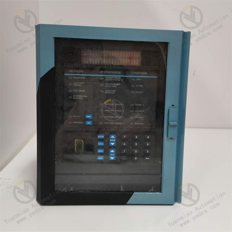
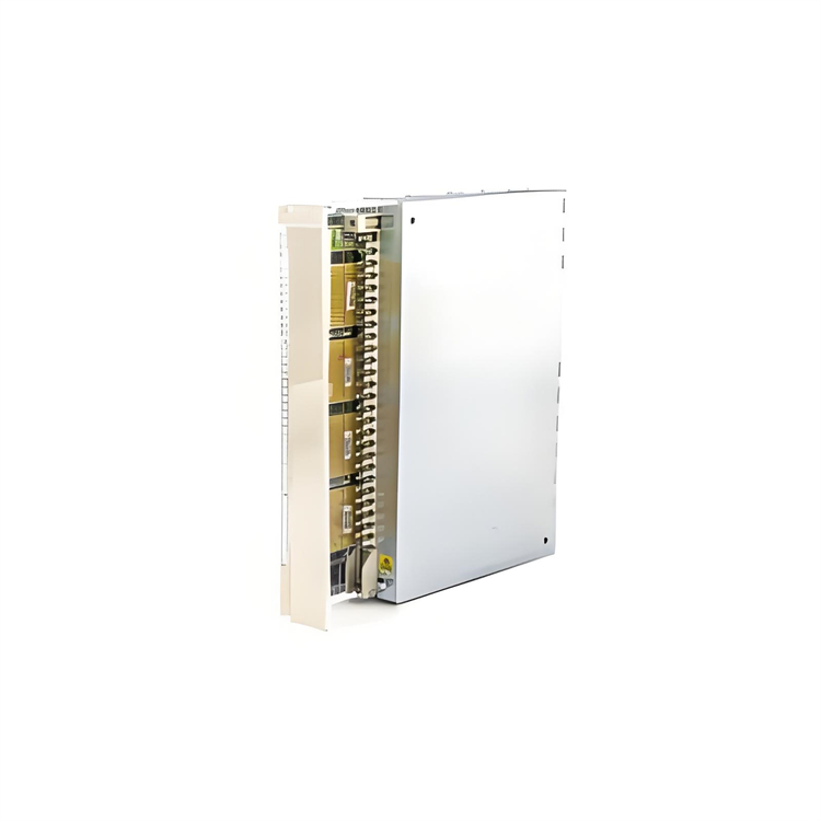
GE Multilin 369-HI-R-M-F-E-H-E
Overview
The GE Multilin 369-HI-R-M-F-E-H-E is a high-performance protective relay and control device tailored for medium-to-high voltage power systems. Engineered to ensure reliable fault detection, circuit protection, and system monitoring, this model integrates advanced protection algorithms, real-time data acquisition, and flexible communication capabilities. It serves as a critical component in industrial, utility, and commercial power distribution networks, combining rugged hardware with configurable software to adapt to diverse system requirements.
Functional Features
- Advanced Protection Capabilities
- Supports comprehensive protection elements: overcurrent (51), earth fault (50N), distance protection (21), directional overcurrent, and transformer differential protection.
- Enables automatic reclosing, breaker failure detection, and adaptive protection schemes for precise fault isolation.
- Configurable time-current characteristics ensure coordination with upstream/downstream devices.
- Real-time Monitoring & Data Logging
- Measures electrical parameters (voltage, current, power, frequency) with high-precision sensors (±0.5% accuracy).
- Captures fault waveforms, event sequences, and disturbance records for post-fault analysis (supports up to [X] event logs).
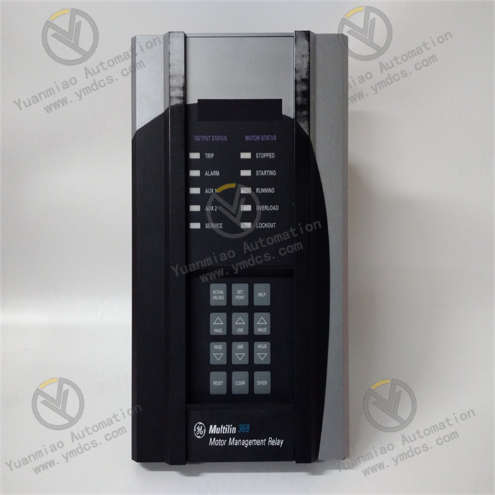
- Displays real-time status via front-panel LCD and LED indicators.
- Flexible Communication Interfaces
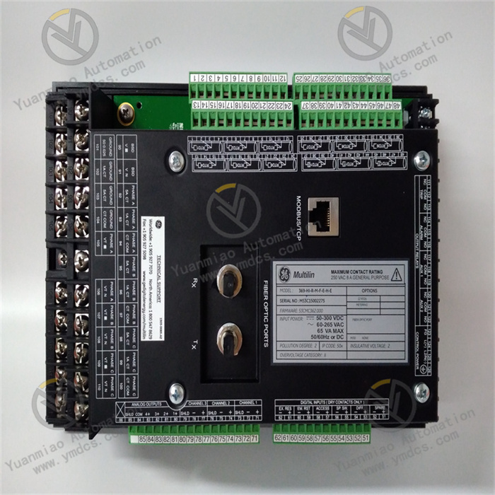
- Equipped with serial ports (RS-232/485), Ethernet (10/100BaseT), and optional fiber optic ports.
- Supports industry-standard protocols: IEC 61850, DNP3, Modbus, and IEEE C37.118 for SCADA integration.
- Enables remote configuration, monitoring, and firmware updates via web interface or GE Multilin ToolSet software.
- User-configurable Operation
- Intuitive HMI for local setup and diagnostics.
- Customizable protection zones, alarm thresholds, and control outputs.
- Multi-level password protection for secure access and configuration.
Technical Parameters
| Category | Specifications |
|---|---|
| Rated Voltage | Control power: 110-250V DC / 100-240V AC; VT inputs: 120V / 220V secondary |
| Current Inputs | CT inputs: 5A or 1A secondary (±0.5% accuracy); support for up to [X] CT channels |
| Communication | 2× RS-485, 1× 10/100BaseT Ethernet, optional IEC 61850-8-1/GOOSE fiber interface |
| Protection Elements | Overcurrent, earth fault, undervoltage (27), overvoltage (59), distance (21), etc. |
| Environmental | Operating temp: -25°C to +70°C; Storage temp: -40°C to +85°C; Humidity: 5%–95% RH (non-condensing) |
| Certifications | Compliant with IEEE, IEC, NEMA, and ANSI standards; CE, UL, and CSA certified |
Working Principle
- Protection Logic Operation
The relay continuously monitors voltage and current signals from CTs/VTs. When parameters exceed preset thresholds (e.g., overcurrent or phase displacement), the microprocessor-based protection algorithm evaluates fault characteristics and triggers trip outputs to isolate the faulted section. Adaptive coordination logic minimizes downtime by only tripping relevant breakers. - Data Acquisition & Processing
Analog inputs are converted to digital signals via high-resolution ADCs, while digital inputs monitor breaker status and external signals. The processor analyzes real-time data, compares it against configured settings, and generates control commands or alarm signals. - Communication & System Integration
Collected data is packaged into protocol-compliant frames (e.g., IEC 61850 GOOSE messages) for transmission to supervisory systems. The relay supports peer-to-peer communication for fast inter-device coordination, enabling seamless integration into smart grid architectures.
Operation Guide
- Installation Preparations
- Verify voltage/current ratings and system topology match the device specifications.
- Prepare tools (screwdriver, multimeter) and ESD protection equipment.
- Mounting & Wiring
- Install the relay in a 19-inch rack or switchgear panel using provided brackets.
- Connect CT/VT cables, control power, trip/close circuits, and communication links per the wiring diagram.
- Ensure proper grounding to mitigate EMI and maintain signal integrity.
- Configuration Steps
- Access the local menu via front-panel buttons to set basic parameters (CT/VT ratios, protection enablement).
- Use GE Multilin ToolSet software for advanced configuration (protection curves, communication protocols, event logging settings).
- Perform functional tests with simulated faults to validate trip responses and communication functionality.
- Troubleshooting
- Power Failure: Check fuse status, power supply voltage, and wiring connections.
- False Tripping: Review protection settings for incorrect time-current curves or threshold values.
- Communication Issues: Verify cable integrity, IP settings, and protocol compatibility; update firmware if necessary.