Description
IS215UCVGH1A
I. Overview
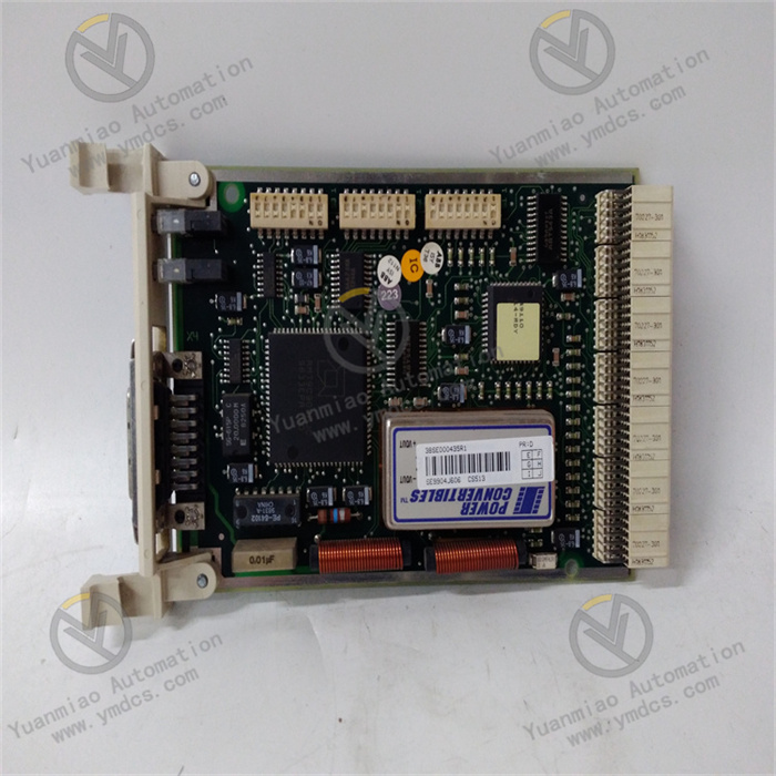
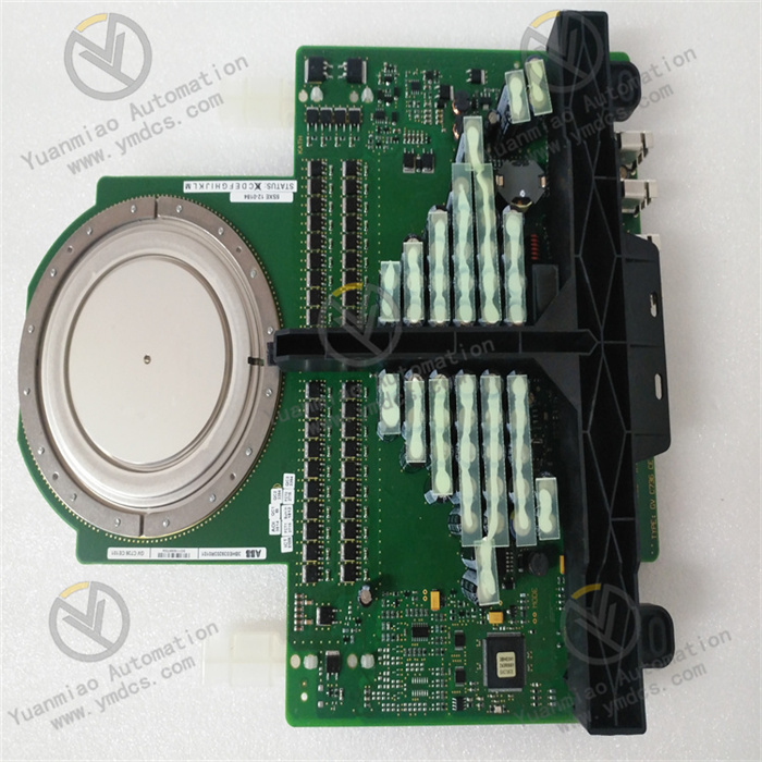
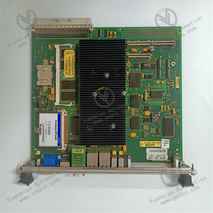
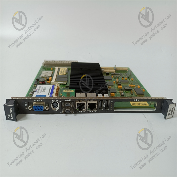
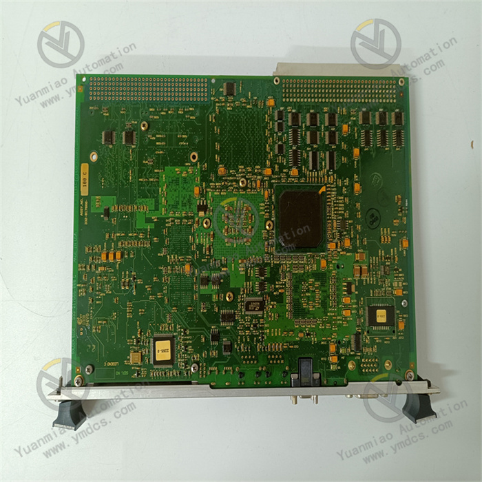
The GE IS215UCVGH1A is a critical control board developed by General Electric (GE) for industrial automation control systems, typically applied in control systems of large power generation equipment such as gas turbines, steam turbines, and complex industrial processes. As one of the core components in the system, it undertakes key tasks such as data processing, signal transmission, and control command execution, playing a vital role in ensuring the stable operation of the entire system. Relying on GE's profound technical accumulation in the field of industrial control, this board features high reliability and strong adaptability, capable of operating stably in harsh industrial environments with high temperatures and strong electromagnetic interference, effectively improving the automation level and efficiency of industrial production.
II. Functional Features
- Efficient Data Processing Capability: Equipped with high-performance processors and data processing chips, it can quickly handle massive data from sensors and other control modules. During the operation of power generation equipment, it can real-time analyze key parameters such as temperature, pressure, and rotation speed, and promptly respond based on preset programs and algorithms to ensure the equipment operates in an optimal state.
- Diverse Signal Interfaces: Equipped with various types of signal interfaces, including analog input/output interfaces and digital input/output interfaces. Analog interfaces can connect to various sensors to achieve precise collection and control of continuously changing physical quantities (such as voltage, current, temperature); digital interfaces are used for switching signal transmission, facilitating interaction with devices such as relays and contactors to meet the connection needs of different industrial equipment and systems.
- Reliable Communication Function: Supports multiple communication protocols such as Modbus and Profibus, enabling stable data communication with upper computers, other control boards, or intelligent devices. Through the communication network, remote monitoring, parameter setting, and program updating can be realized, facilitating operators to centrally manage and maintain the system.
- Powerful Fault Diagnosis and Protection Mechanism: Features a complete self-diagnosis function, which can real-time monitor the operating status of the board itself and connected devices. Once anomalies such as hardware faults, data errors, or communication interruptions are detected, it can quickly issue alarms through indicator lights, alarm signals, etc., and automatically take protective measures such as cutting off the power supply of the faulty part and stopping the operation of related equipment to prevent the expansion of faults and reduce equipment damage and production losses.
- Flexible Programming and Configuration: Supports users in functional programming and parameter configuration through dedicated programming software. According to different industrial application scenarios and control requirements, personalized control logic and operating parameters can be customized, enabling the board to exert optimal performance in various complex industrial control systems.
III. Technical Parameters
- Operating Voltage: [Specific voltage value, such as 24VDC±10%]
- Operating Temperature Range: [X]°C ~ [X]°C (e.g., -40°C ~ +70°C, to be determined based on the actual product)
- Storage Temperature Range: [X]°C ~ [X]°C (e.g., -55°C ~ +85°C, to be determined based on the actual product)
- Analog Input Channels: [X] channels, input signal range [specific range, such as 0 - 10V, 4 - 20mA]
- Analog Output Channels: [X] channels, output signal range [specific range, such as 0 - 10V, 4 - 20mA]
- Digital Input Channels: [X] channels, input level standard [specific standard, such as TTL level]
- Digital Output Channels: [X] channels, output driving capability [specific capability, such as can drive 500mA load]
- Communication Interfaces: Supports protocols such as Modbus and Profibus, interface types [specific types, such as RS-485, RS-232, Ethernet interface]
IV. Working Principle
When the GE IS215UCVGH1A is connected to the industrial control system, the power module first converts the external input power into stable voltages required by each component of the board, providing power guarantee for the normal operation of the board. Signals generated by external devices (such as sensors and actuators) are transmitted to the board through the corresponding analog or digital interfaces.
For analog signals, they first go through preprocessing such as amplification and filtering by the signal conditioning circuit, and then are converted into digital signals by the A/D converter and sent to the processor of the board for analysis and processing; digital signals can be directly read by the processor. The processor performs calculations and logical judgments on the collected data according to pre-written control programs and algorithms, generating corresponding control commands.
These control commands are transmitted to the actuators (such as motors, valves, etc.) through the D/A converter (for analog control commands) or directly through the digital output interface to control the operating status of the equipment. At the same time, the board interacts with other devices or upper computers through the communication interface, uploading the system operating status and collected data, and receiving control commands and parameter settings from the upper computer to achieve coordinated control of the entire industrial control system. During operation, the fault diagnosis module continuously monitors the status of the board's internal circuits, each interface signal, and connected devices, and once an anomaly is found, it immediately triggers the alarm and protection mechanism.
V. Common Faults and Solutions
- Board Fails to Start
- Fault Phenomenon: After powering on, the board shows no response, the indicator light does not turn on, and the system cannot enter the working state.
- Solutions: First, check whether the external power supply is normal, measure whether the input voltage is within the specified range, and check whether the power connection cable is loose or damaged; if the power supply is normal, check the power module on the board for obvious signs of damage such as burned components or bulging capacitors, and replace the damaged power module if any; if the power module is fine, try resetting the board. If it still cannot start, it may be a fault in key components such as the processor or chipset on the motherboard, and professional maintenance personnel should be contacted for detection and repair.
- Abnormal Signal Collection
- Fault Phenomenon: Analog or digital input signals cannot be collected normally, and the collected data is inaccurate or no data is output.
- Solutions: For abnormal analog collection, check whether the sensor is working normally and measure whether the sensor output signal is within the normal range; check whether the connection cable of the analog input interface is loose, short-circuited, or open-circuited; check whether the configuration parameters of the analog input channel on the board are correct, such as range settings and filter parameters; if the above are all normal, it may be a fault in the board's A/D conversion circuit, which requires professional maintenance. For abnormal digital collection, check whether the digital input device (such as switches, sensors) is working normally and whether the input level meets the board's requirements; check whether the wiring of the digital input interface is correct and whether there is poor contact; if the device and wiring are both normal, it may be a fault in the board's digital input circuit, which requires further detection and repair.
- Communication Failure
- Fault Phenomenon: The board cannot establish a communication connection with the upper computer or other devices, or problems such as data loss and errors occur during communication.
- Solutions: Check whether the communication cable is correctly and firmly connected and whether there is any damage; confirm whether the type of communication interface and the setting of communication protocols are consistent with the connected device, including parameters such as baud rate, data bits, stop bits, and parity bit; check whether the IP addresses of the board and the connected device (if using Ethernet communication) are in the same network segment; try replacing the communication interface or communication cable for testing; if the above operations are ineffective, it may be a fault in the board's communication module, which requires professional inspection and repair.
- Abnormal Control Command Output
- Fault Phenomenon: The control commands issued by the board cannot make the actuator operate normally, or the actuator operates abnormally.
- Solutions: Check whether the actuator is working normally, whether the power is turned on, and whether there is any jamming in the mechanical part; check whether the wiring of the board's control command output interface is correct and whether there is any looseness or short circuit; measure whether the control command output signal is normal. For analog output, check whether the output voltage or current is within the specified range; check whether the board's control program and parameter settings are correct and whether there are logical errors; if the actuator and wiring are both normal, it may be a fault in the board's D/A conversion circuit (for analog output) or digital output drive circuit, which requires professional maintenance.