Description
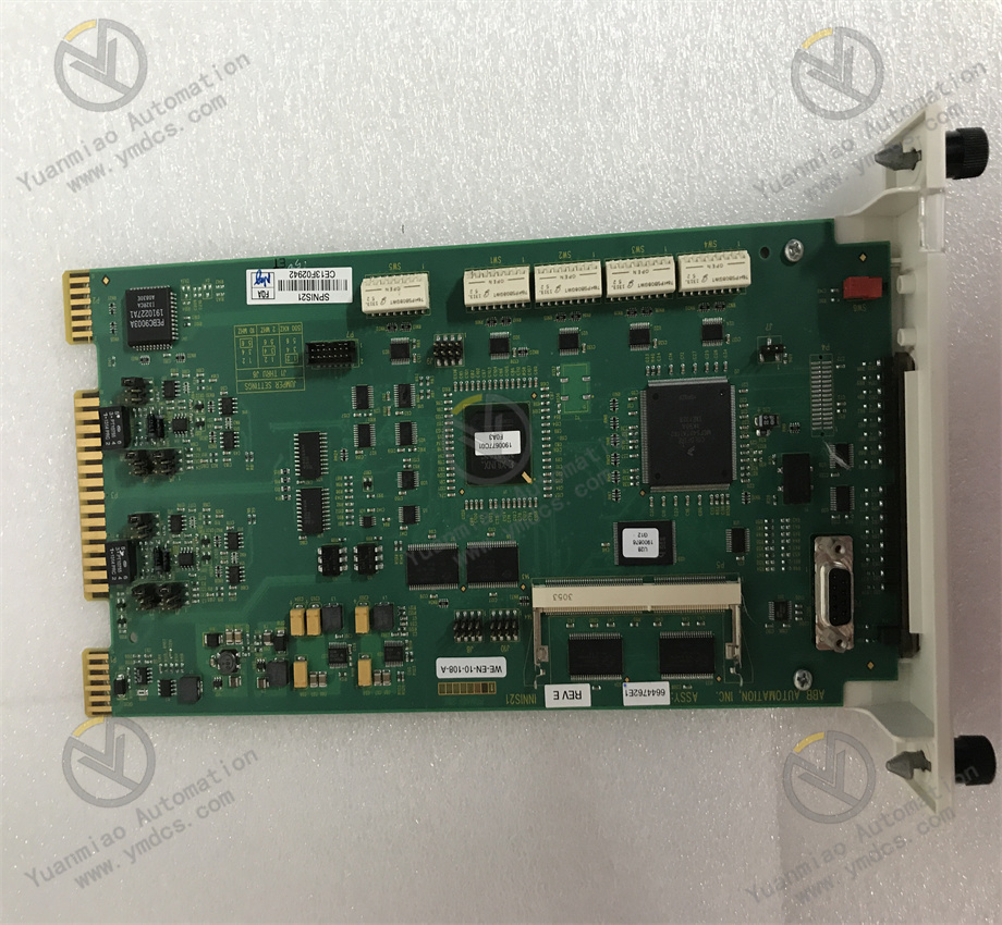
ABB CI520V1 3BSE012869R1
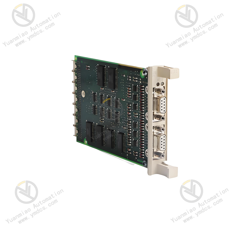
ABB CI520V1 3BSE012869R1 is a serial communication interface module primarily used to enable serial communication (e.g., RS-232/RS-485 protocols) between devices in industrial automation systems. It supports data interaction with sensors, actuators, third-party controllers, and other devices, making it suitable for scenarios requiring reliable serial communication, such as production line monitoring, process control, and building automation.
Technical Parameters
| Parameter | Description |
|---|---|
| Power Supply Voltage | 24V DC (typical industrial-grade power supply, supporting a certain voltage range) |
| Communication Interface | Supports RS-232/RS-485 standard interfaces, adaptable to different communication distances and topologies |
| Baud Rate Range | Maximum support: [Specific baud rates refer to the manual; typically, industrial-grade modules support 1200 bps–115200 bps] |
| Data Format | Supports custom data bits (5–8 bits), stop bits (1–2 bits), and parity (none/odd/even) |
| Number of Channels | [To be confirmed as single-channel or multi-channel; typical industrial modules may have 1–2 independent communication channels] |
| Electrical Isolation | Features electrical isolation with strong anti-interference capability, protecting the module from surges and noise |
| Operating Temperature | -40°C to +70°C (wide-temperature design, adapting to harsh industrial environments) |
| Protection Level | Typically IP20 (suitable for installation inside control cabinets) |
Product Features
High Compatibility
- Supports multiple serial communication protocols (e.g., Modbus RTU, custom protocols) and can interface with devices from different manufacturers.
- Flexible parameter configuration (sets baud rate, parity bit, etc., via software or module DIP switches).
Industrial-Grade Reliability
- Designed and manufactured to ABB’s rigorous quality standards, with anti-vibration and electromagnetic compatibility (EMC) capabilities.
- Supports redundant power input design (for some models) to ensure system stability.
Convenient Installation and Maintenance
- Supports standard DIN rail mounting or screw fixation, adapting to mainstream control cabinet layouts.
- Module status indicator lights (e.g., power, communication transmission/reception status) visually display operating conditions for easy fault troubleshooting.
System Integration Capability
- Can seamlessly access controllers such as ABB AC 500 series, with parameter configuration and communication debugging via programming software (e.g., CodeSys).
Common Communication Fault Troubleshooting Methods
When the module experiences communication anomalies, follow these troubleshooting steps:
Hardware Connection Check
- Power Supply: Use a multimeter to measure the input voltage to ensure it is 24V DC (±10%), and inspect terminals for looseness or oxidation.
- Communication Cables:
- RS-232: Confirm whether the cable is straight-through or cross-wired (based on the device type), and check for bent or damaged interface pins.
- RS-485: Ensure the bus uses differential signal connections, proper termination resistors (e.g., 120Ω) are installed, and the cable shield is well-grounded.
- Grounding: Check that the module’s grounding terminal is reliably grounded to avoid ground loop interference.
Communication Parameter Matching
- Verify that the module’s baud rate, data bits, stop bits, and parity bits fully match those of the communication peer device.
- For multi-slave networks (e.g., RS-485 buses), check that the module’s slave address is unique and conflict-free.
Module Status Diagnosis
- Judge status via indicator lights:
- Power Light (PWR): Off → Power failure or module damage.
- Communication Lights (TX/RX): Should flash during normal communication; constant on or off → Possible no data transmission or link interruption.
- Use a serial debugging tool (e.g., PC-based serial assistant) to directly communicate with the module and test data transmission and reception.
Software and Configuration Check
- Confirm that the communication protocol type (e.g., Modbus master/slave) and parameter configuration for the module in the programming software are correct.
- Check whether the invocation of communication function blocks (e.g., Modbus read/write instructions) in the program complies with timing requirements to avoid communication conflicts.
Replacement and Isolation Testing
- Replace with a normal module of the same model to determine if it is a hardware failure (e.g., chip damage, interface burnout).
- Isolation method: Disconnect other devices on the bus one by one to test if the module can communicate normally with a single device, troubleshooting interference from other devices or excessive bus load.
Environmental and Interference Troubleshooting
- Check for strong electromagnetic sources (e.g., motors, frequency converters) in the vicinity. It is recommended to route communication cables separately from power cables and use shielded twisted-pair cables.
- Measure the bus signal waveform (using an oscilloscope) to observe for signal attenuation, distortion, or noise interference.
Application Scenarios
- Manufacturing: Connects PLCs with robots and CNC machines to enable program transmission and status monitoring.
- Energy and Power: Interfaces with smart meters and sensors to collect real-time data and upload it to monitoring systems.
- Water Treatment: Controls devices such as water pumps and valves via serial communication to achieve automated process control.