Description
1. Product Overview
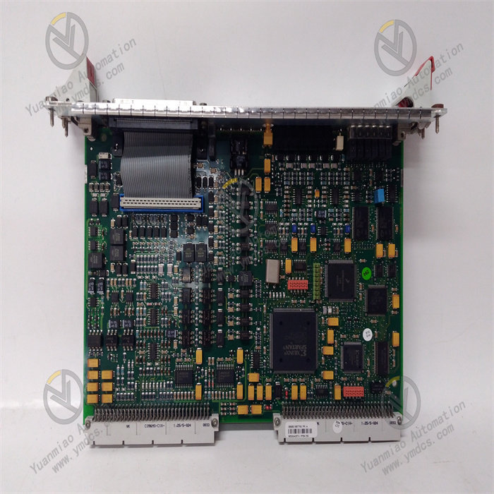
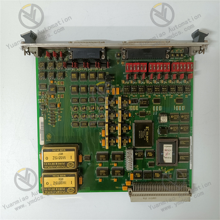
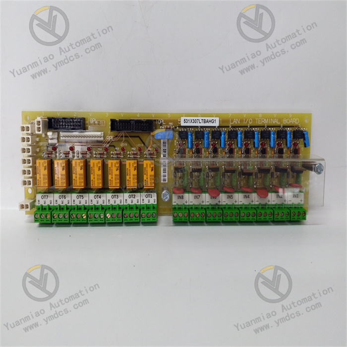
GE 531X307LTBAFG1 is a dedicated LAN terminal interface board for the EX2000 excitation system under General Electric industrial control systems. As core supporting hardware of the GE EX2000 series generator‑set excitation control system, it serves as a dedicated terminal hub for local signal terminal docking, low‑voltage logic output, high‑voltage relay drive and LAN bus data interaction of the excitation system.
Designed for excitation systems of synchronous generator sets in thermal‑power, hydropower and combined‑cycle gas‑turbine power plants, this board implements core functions including local discrete‑signal access for excitation systems, push‑button operation signal acquisition, interlock loop signal matching, low‑voltage logic signal output, high‑voltage relay drive, local terminal signal transfer and LAN bus communication transmission. It realizes accurate transfer and logic conversion of local operation signals, interlock protection signals and status feedback signals of the excitation system, and interconnects excitation main‑control boards, local operation panels, high‑voltage drive loops and upper‑level control systems. It is the critical terminal hardware ensuring stable local loops, reliable interlock and coordinated communication of generator‑set excitation systems.
This product strictly complies with GE EX2000 original excitation‑system design specifications, IEC power‑equipment safety standards and EMC industrial specifications. It has passed a full set of rigorous power‑grade tests, including full‑load power‑on aging, high‑low temperature cyclic testing, continuous vibration shock, high‑voltage insulation withstand, electromagnetic interference resistance and contact switching‑life test. Supporting 24/7 year‑round full‑load operation, it withstands harsh power‑plant cabinet conditions such as high enclosed temperature, dust‑laden humidity, alternating temperature cycles, sustained equipment vibration, heavy electromagnetic interference and minor grid fluctuation.
It addresses common drawbacks of traditional excitation terminal boards, such as signal‑transfer deviation, poor contact of contacts, chaotic logic signals, unstable relay drive, LAN communication stuttering and loop aging after long‑term service. As essential hardware for new‑build EX2000 excitation‑system assembly, technical‑retrofit replacement of aged terminal boards, rectification of abnormal local‑signal loops and strategic spare‑part storage for core power‑plant units, it guarantees reliable local operation, precise interlock protection, stable bus communication and controllable system coordination for generator‑set excitation systems.
2. Functional Features
2.1 Multi‑channel Local‑signal Transfer with Accurate and Stable Logic Matching
As dedicated terminal‑interface hardware for the EX2000 excitation system, the 531X307LTBAFG1 integrates multiple standardized signal terminals for centralized acquisition of discrete signals such as local push‑button commands, local selector‑switch status, equipment interlock feedback and unit status contacts. It performs signal filtering, shaping, level conversion and logic matching. It accurately interfaces with excitation main‑control logic loops, converting local passive contacts and active operation signals into standard logic signals recognizable by the system. It thoroughly avoids excitation operation failure, false interlock triggering and abnormal status feedback caused by local‑signal noise, level mismatch and signal distortion, and ensures full synchronization between local‑operation and remote‑control logic of the excitation system.
2.2 Multi‑channel Relay‑drive Output for Coordinated High‑low‑voltage Loop Operation
The board is equipped with 7 built‑in C‑type low‑voltage relay contact output loops (OT1‑OT7). Each channel delivers independent low‑current drive signals to actuate high‑current high‑voltage relay modules of the excitation system, realizing galvanic isolation and coordinated control between high‑voltage and low‑voltage loops. Low‑voltage logic circuits and high‑voltage execution circuits operate independently in separate layers to prevent main‑control‑unit damage induced by high‑voltage reverse breakdown and voltage crosstalk. It reliably executes logical actions including excitation system enable/disable, startup/shutdown, interlock blocking and fault tripping. Relay contacts feature fast response, dependable actuation, anti‑adhesion and anti‑false‑trigger performance, satisfying frequent condition switching and interlock‑protection requirements of generator‑set excitation systems.
2.3 Native LAN Bus Communication for Efficient System‑wide Data Exchange
Featuring dedicated LAN‑terminal communication architecture natively compatible with GE EX2000 excitation‑system bus protocol, the board acts as a local communication hub for the excitation system. It aggregates and uploads local status data, operation logs, fault‑contact information and loop operating parameters, and distributes main‑control commands. It seamlessly connects excitation main‑control systems, power‑plant DCS, PLC and SCADA platforms to implement real‑time upload of local operating conditions, remote feedback of operation status, accurate reporting of fault signals and synchronization of system configuration commands. No additional adapter modules are required. The communication link delivers high stability and low latency, and fits both legacy and new‑build EX2000 excitation‑system automation architectures.
2.4 Power‑grade Anti‑interference Design for Stable Performance under Complex Conditions
Adopting power‑specific reinforced electrical architecture and multi‑layer electromagnetic shielding, with physical isolation and partition layout for strong‑current and weak‑current circuits, it achieves superior EMC performance. It effectively mitigates interference sources in power plants such as radiation from excitation transformers, harmonic noise from frequency converters, coupling interference from high‑voltage power cables, grid voltage fluctuation and line induced noise. During runtime, no signal drift, logic disorder or false contact actuation occurs. In harsh cabinet environments with high enclosed temperature, dust‑laden humidity, temperature cycling, continuous vibration and heavy electromagnetic interference, it maintains stable terminal‑loop contact, precise signal transmission and dependable relay operation, preventing unit anomalies originating from local excitation‑loop faults.
2.5 Full‑condition Intelligent Self‑diagnosis for Precise Fault Tracing
Dual hardware‑and‑software self‑diagnosis continuously monitors board power‑supply status, LAN bus communication link, terminal‑signal access status, relay‑contact conditions, loop continuity and hardware health. It accurately identifies anomalies such as loose terminals, wire breakage, contact degradation, communication interruption and loop failure, actively reports fault codes and fault locations, and supports fault tracing and condition analysis. It helps maintenance personnel rapidly locate hidden defects in local loops, reduces troubleshooting workload for excitation systems, and improves unit maintenance efficiency and equipment reliability.
2.6 Standardized Modular Design for Convenient Maintenance and Replacement
It adopts standardized modular hot‑swap structure for GE EX2000 excitation systems, delivering precise rack positioning, easy disassembly and secure latching to match original cabinet layout. Standardized terminal interfaces and loop definitions ensure orderly wiring, reliable contact and convenient servicing. Lossless in‑situ replacement of defective legacy terminal boards is supported without modifying local field wiring, resetting system configuration or shutting down the unit. It applies to non‑shutdown technical retrofits, emergency fault repair and routine‑loop maintenance, lowering O&M costs and unit outage losses for power‑plant excitation systems.
3. Technical Specifications
3.1 Core Adaptation Parameters
- Model: 531X307LTBAFG1
- Brand: General Electric (GE)
- Series: Supporting board for GE EX2000 generator‑set excitation system
- Type: LAN Terminal Interface Board, Local‑signal Transfer & Drive Board
- Compatible Systems: GE EX2000 excitation control system, power‑plant DCS / PLC / SCADA
- Applicable Equipment: Synchronous excitation equipment for large steam‑turbine generators, hydro‑generators and gas‑turbine generator sets
- Core Functions: Local‑operation / interlock signal acquisition, signal level conversion, 7‑channel C‑type relay‑drive output, LAN bus data exchange, loop‑condition self‑diagnosis, fault‑alarm reporting, high‑low‑voltage loop coordination
- Application Scenarios: New‑build EX2000 excitation‑system assembly, replacement of aged terminal boards, rectification of abnormal local‑signal loops, technical retrofit & upgrade of excitation‑system logic loops, strategic spare‑part storage for core power‑plant units
3.2 Electrical Performance Parameters
- Operating Voltage: Compatible with standard power‑plant control AC/DC power supply; wide‑range support for 24‑230 V AC and 24‑250 V DC
- Operating Current: 4‑10 mA peak under AC conditions; 4‑8 mA under DC conditions; stable low‑power operation
- Relay Output: 7‑channel OT1‑OT7 C‑type low‑voltage relay contact outputs, dedicated high‑voltage relay drive loops
- Supported Signal Types: Local passive contacts, active discrete operation signals, interlock feedback signals
- Communication Bus: Dedicated EX2000‑system LAN terminal bus for high‑speed stable bidirectional data exchange
- Isolation Performance: Physical isolation between strong‑current and weak‑current circuits; galvanic isolation for high‑voltage / low‑voltage loops to suppress crosstalk and high‑voltage back‑feed
- Anti‑interference Feature: Multi‑layer electromagnetic‑shielding architecture, tolerant to heavy power‑plant EMI and grid‑harmonic fluctuation
- Electrical Stability: 24/7 full‑load continuous operation; no contact adhesion, signal drift or communication dropout
3.3 Operating Condition Parameters
- Operation Mode: 24/7 year‑round online operation and signal scheduling
- Response Performance: Microsecond‑level response for signal acquisition, logic conversion and relay actuation, zero lag
- Interaction Performance: Real‑time LAN‑bus data upload, main‑control‑command distribution and configuration‑parameter synchronization
- Stability Feature: No routine calibration or frequent maintenance; consistent long‑term logic performance and extended contact service life
- Diagnostic Capability: Comprehensive self‑check and alarm covering power supply, communication, terminal loops, relay status and hardware faults
3.4 Environmental Specifications
- Operating Temperature: 0 ℃ ~ +65 ℃, power‑grade range for enclosed power‑plant cabinet operation
- Storage Temperature: ‑40 ℃ ~ +85 ℃, suitable for extreme conditions during storage and transportation
- Operating Humidity: 5% ~ 95% RH (non‑condensing), resistant to dusty high‑humidity cabinet environment in power plants
- Environmental Durability: Dust‑proof, moisture‑proof, temperature‑cycle aging resistance, anti‑vibration, anti‑strong‑electromagnetic‑interference
- Compliance: Compliant with IEC power‑electrical‑safety, EMC and generator‑set excitation‑control industry standards
3.5 Physical Parameters
- Mounting Method: EX2000‑system standard rack‑mount modular plug‑in installation; precise positioning and easy assembly
- Form Factor: Integrated industrial terminal board, compact layout saving cabinet space
- Material: Industrial flame‑retardant reinforced PCB with insulating housing; anti‑loosening, wear‑resistant, aging‑resistant, flame‑retardant and moisture‑proof
- Structural Feature: Partition layout separating strong‑current and weak‑current circuits, independent high‑/low‑voltage loops eliminating signal crosstalk and high‑voltage interference
- Interfaces: Multiple standardized signal terminals, LAN bus ports and relay output connectors; standardized wiring and reliable contact
4. Hardware Configuration & Structural Advantages
4.1 Core Hardware Configuration
The GE 531X307LTBAFG1 adopts EX2000‑excitation‑system‑specific LAN‑terminal hardware architecture. Core components include multi‑channel local‑signal conditioning units, level‑conversion modules, seven independent C‑type relay‑drive loops, LAN‑bus communication processors, hardware self‑diagnosis circuits, multi‑stage electromagnetic‑shielding circuits and stabilized power‑supply modules.
Internal physical partitioning separates strong‑current and weak‑current circuits while high‑voltage and low‑voltage loops are galvanically isolated, fundamentally preventing signal distortion, logic disorder, false‑contact actuation and communication anomalies induced by high‑voltage back‑feed, power‑supply fluctuation and electromagnetic crosstalk. All critical components pass strict original‑factory screening: full‑load aging, high‑low‑temperature thermal shock, high‑voltage insulation test, EMI test and contact‑life evaluation. Optimized for continuous generator‑set excitation‑system operation, frequent condition switching and harsh power‑plant electromagnetic environments, it independently completes the full workflow: local‑signal acquisition, conditioning conversion, logic matching, relay drive, bus data exchange and loop fault alarming. It delivers outstanding performance: strong signal adaptability, high loop stability, dependable contact operation, communication noise immunity and no long‑term performance degradation.
4.2 Structural Design Advantages
The board features compact standardized modular construction optimized for dense installation inside EX2000 excitation‑system cabinets for high space‑utilization and neat arrangement. Built with flame‑retardant, moisture‑proof and anti‑vibration reinforced materials, circuits and relay assemblies are mechanically secured against loose connections, terminal loosening and poor‑contact faults caused by sustained cabinet vibration, temperature cycling and dusty‑humid atmosphere.
Clearly‑partitioned standardized terminals simplify field wiring, maintenance and loop troubleshooting. Lossless in‑situ replacement of faulty legacy boards is achievable without rewiring or reconfiguring control logic, greatly cutting costs for excitation‑system retrofits, maintenance and emergency repair to satisfy long‑term stable terminal‑loop protection requirements of large‑scale generator‑set excitation systems.
5. Working Principle
The GE 531X307LTBAFG1 LAN terminal interface board implements closed‑loop intelligent terminal control workflow: Local‑signal Input → Signal Conditioning & Level Conversion → Logic Matching & Validation → Relay‑drive Output → LAN Bus Data Exchange → Full‑condition Self‑diagnosis & Alarm, enabling accurate local‑signal transfer, reliable logic execution and stable data exchange for EX2000 excitation‑system local loops.
During operation, discrete signals such as local push‑button commands, selector‑switch status and equipment interlock feedback of the excitation system enter standardized terminal loops of the board. Multi‑stage filtering, shaping and level‑conversion units eliminate field electromagnetic noise, line chattering and interference, converting non‑standard local signals into standard logic signals recognizable by the excitation main‑control system. Signal validation and logic matching ensure authenticity without distortion or deviation for local operation commands and interlock signals.
Validated standard logic signals are transmitted in two directions. On one path, signals are sent to excitation main‑control boards for logical computation, condition judgment and interlock protection. On the other path, they actuate seven on‑board independent C‑type relay output loops, generating low‑voltage drive signals to trigger high‑power high‑voltage relay modules and execute excitation‑system startup/shutdown, enable/disable, fault blocking and interlock protection. Safe galvanic isolation and precise coordination between high‑voltage and low‑voltage loops are realized. Meanwhile, via the dedicated LAN bus, the board uploads real‑time local‑loop conditions, relay status, operation logs and fault information to upper‑level systems, and receives main‑control configuration and remote‑control commands to achieve seamless coordinated local‑and‑remote control of the excitation system.
Dual hardware‑and‑software self‑diagnosis runs throughout operation to continuously monitor power‑supply health, LAN communication links, terminal‑signal loops, relay‑contact conditions and hardware status. Upon detection of signal abnormality, loop failure, communication dropout or contact degradation, affected loops are locked, fault codes are reported and system alarms are triggered to contain single‑point‑fault propagation, safeguarding stable local‑loop performance, accurate logic, dependable interlock and unobstructed communication for the EX2000 excitation system.
6. Application Scenarios
6.1 Core Local‑terminal Signal Transfer for EX2000 Excitation Systems
As the exclusive matching LAN‑terminal‑interface hardware for GE EX2000 excitation systems, it is widely deployed in excitation control systems for large synchronous generator sets in thermal‑power, hydropower and gas‑turbine plants. It performs full‑volume transfer and logic conversion for local operation, interlock feedback and status signals. Serving as the key interconnecting hub among local operation panels, field execution loops and main‑control systems of excitation systems, it guarantees consistency and reliability for local operation, remote control and interlock protection, and constitutes fundamental mandatory hardware for commissioning excitation systems.
6.2 High‑low‑voltage Loop Coordinated Drive and Interlock‑protection Execution
Leveraging seven independent relay‑drive outputs, it reliably actuates high‑voltage execution loops of excitation systems and precisely implements condition switching and fault‑interlock actions. High‑low‑voltage galvanic‑isolation design protects main‑control units against high‑voltage surge damage, significantly improving safety and fault tolerance of excitation systems. It responds accurately to unit startup‑shutdown, load adjustment and fault events, and cooperates with main‑control systems for excitation regulation and safety blocking to mitigate major risks such as excitation runaway and abnormal unit grid‑connection.
6.3 Strategic Spare‑part Storage for Core Power‑plant Units
The 531X307LTBAFG1 is a critical spare part for GE EX2000 excitation systems. Terminal‑loop failure, relay degradation or communication interruption can directly cause local excitation‑operation failure, interlock‑protection disablement and system communication dropout, which may lead to severe production incidents including abnormal excitation, failed grid‑synchronization and unplanned unit outages. As stored strategic spare hardware, it enables fast in‑situ emergency swap‑out of faulty boards to rapidly restore excitation‑system terminal‑loop and communication functions for continuous unit operation. It is essential for maintenance, emergency repair, system expansion and hardware upgrade of large‑scale power‑plant units.