Description
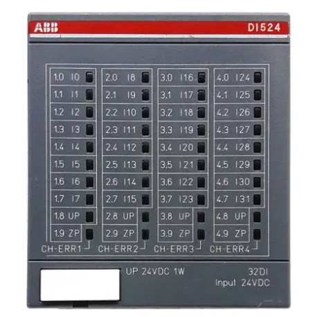
ABB DI524 1SAP240000R0001
I. Overview
ABB DI524 1SAP240000R0001 is a digital input module, designed to collect, electrically isolate and condition various digital signals in industrial field (such as equipment switch status, limit switch signals, button trigger signals, etc.). It accurately converts field signals into standard logic signals recognizable by the PLC master control unit, realizing real-time monitoring and data feedback of the operating status of field devices. It serves as a key signal hub connecting field sensors/actuators and the PLC control system.
As a core component of industrial automation control systems, this module features excellent signal acquisition capability and environmental adaptability. Adopting industrial-grade components and optimized circuit design, it can operate stably for a long time under complex industrial working conditions. It is widely used in multiple core industrial fields such as manufacturing, energy and transportation, and is also suitable for automation control scenarios in segmented industries including electric power, elevators, intelligent parking, automobile manufacturing, steel and glass, providing reliable signal support for the stable operation of various industrial equipment. At present, the market supply channels are mature, which can fully meet the accessory supporting needs of industrial equipment maintenance and replacement, system upgrading and transformation, and new construction projects. Moreover, the product has formal certifications and provides comprehensive quality assurance.
II. Product Features
Multi-channel High-efficiency Signal Acquisition: Equipped with 32 independent digital input channels, it can simultaneously collect multiple channels of field digital signals in parallel, greatly improving signal acquisition efficiency. It can fully meet the field status monitoring needs of multi-device and multi-node scenarios, and is suitable for signal acquisition applications of large-scale industrial automation control systems.
High-reliability Industrial-grade Design: Strictly complying with ABB's design standards for industrial automation products, it selects high-quality industrial-grade components and precision manufacturing processes, and has passed rigorous environmental stress screening and reliability verification. It has excellent anti-electromagnetic interference capability and operational stability, can effectively resist electromagnetic radiation generated by equipment such as frequency converters and high-power motors in industrial field, and significantly reduce the failure rate under complex working conditions.
Flexible Wiring and Adaptability: Adopting 1-wire system wiring mode, it is compatible with 24VDC input signals and can support various types of field sensors such as dry contacts and wet contacts. With good versatility, it can flexibly adapt to different types of field signal acquisition needs and simplify on-site wiring processes.
Comprehensive Isolation and Protection Mechanism: Built-in electrical isolation circuits between channels, effectively avoiding signal crosstalk between channels and damage to the module and PLC master control unit caused by ground potential difference. It integrates functions such as signal filtering and overvoltage protection, which can effectively suppress the impact of signal jitter, voltage fluctuation and field interference on the collected signals, ensuring the accuracy and stability of signal acquisition.
- Convenient Operation & Maintenance and System Adaptability: Adopting modular plug-and-play design, it is easy to install and disassemble, and can be put into use quickly without complex on-site debugging. The module is equipped with clear status indicator lights, allowing operation and maintenance personnel to intuitively monitor the signal acquisition status of each channel and quickly locate faulty channels, thus greatly shortening maintenance downtime. Meanwhile, as a dedicated supporting module for the S500 (AC500) series, it can be perfectly compatible with the same series of PLC master control units, realizing high-speed data interaction through the backplane bus and simplifying the system integration process.
III. Technical Parameters
1. Core Basic Parameters
- Product Model: DI524 1SAP240000R0001
- Product Series: Supporting I/O Module for ABB S500 (AC500) Series Programmable Controllers
- Product Type: Industrial-grade Digital Input Module
- Manufacturer: ABB (ASEA Brown Boveri)
- Order Number: DI524 1SAP240000R0001
- HS Code: 852852
- Product Certification: With formal industrial product certifications
- Mounting Method: Modular Plug-and-play Installation (compatible with S500/AC500 series standard backplanes)
- Core Functions: Digital Signal Acquisition, Electrical Isolation, Signal Conditioning, Status Monitoring and Feedback
- Application Scenarios: Industrial automation scenarios in manufacturing, energy, transportation, electric power, elevators, intelligent parking, automobile manufacturing, steel, glass and other industries
2. Electrical Performance Parameters
- Working Voltage: 24VDC (compatible with industrial standard power supply environment)
- Number of Input Channels: 32-channel Digital Input (independent channel design, supporting parallel acquisition)
- Input Signal Type: Compatible with dry contact/wet contact signals
- Wiring Method: 1-wire System Wiring
- Output Frequency: 30kHz
- Isolation Method: Electrical Isolation between Channels (ensuring signal acquisition stability)
- Signal Conditioning: Integrating signal filtering and shaping functions, effectively suppressing interference signals
3. Environmental and Physical Parameters
- Operating Temperature: -25℃ to +70℃ (wide-temperature design, suitable for extreme industrial environments)
- Storage Temperature: -40℃ to +85℃
- Relative Humidity: 5% to 95% (no condensation, suitable for high-humidity industrial scenarios)
- Protection Class: IP20 (module body, suitable for installation in control cabinets, dust-proof and solid foreign object intrusion prevention)
- Electromagnetic Compatibility: Compliant with industrial-grade electromagnetic compatibility standards, with strong anti-electromagnetic interference capability
- Module Dimensions: Standardized Installation Dimensions (compatible with S500/AC500 series standard racks, subject to the actual product)
- Weight: Approximately 0.5-0.8kg (subject to the actual product)
IV. Working Principle
The core working principle of the ABB DI524 1SAP240000R0001 digital input module is a closed-loop signal processing process of "Signal Acquisition - Isolation and Conditioning - Logic Conversion - Data Transmission - Status Feedback". Through the collaborative work of multiple internal functional units, it realizes the safe, accurate and efficient transmission of field digital signals to the PLC master control unit. The specific working process can be divided into five core stages:
Stage 1: Power Input and Protection StageExternal industrial 24VDC power supply is connected to the module through a standardized power interface. The built-in power protection circuit of the module starts working immediately, providing overvoltage, overcurrent and reverse connection protection for the input power supply. Meanwhile, it filters out clutter and high-frequency interference signals in the power supply, and outputs stable and pure supply voltage, providing safety guarantee for the normal operation of each functional unit inside the module.
Stage 2: Field Signal Acquisition StageThe module collects various field digital signals in real time through 32 independent input channels, including dry contact signals (such as the on-off status of mechanical limit switches and manual buttons) and wet contact signals (such as high and low level signals output by photoelectric sensors and proximity switches). The filter circuit at the front end of the input channel performs preliminary processing on the collected signals, filtering out high-frequency noise and interference pulses in the signals, and providing a clean and stable signal source for subsequent signal conditioning.
Stage 3: Isolation, Conditioning and Logic Conversion StageThe preliminarily filtered signals enter the internal isolation unit. The electrical isolation circuit realizes electrical isolation between the input signals and the module's internal circuit, completely eliminating the impact of strong field electromagnetic interference and ground potential difference on the module's core circuit and the PLC master control unit. The isolated signals enter the signal shaping and conditioning circuit, and after waveform restoration and level calibration, they are converted into standard digital logic signals (0/1) recognizable by the PLC master control unit, ensuring the stability and consistency of the signals.
Stage 4: Data Buffering and Communication Transmission StageThe converted standard logic signals are temporarily stored in the high-speed data buffer area inside the module to avoid data loss. The module establishes a stable communication link with the ABB S500 (AC500) series PLC master control unit through the backplane bus, and uploads the signal status data of 32 channels to the master control unit in batches at high speed. Meanwhile, it receives configuration commands issued by the master control unit (such as acquisition frequency adjustment, channel enable/disable, etc.) to complete the dynamic configuration of the module's working parameters.
Stage 5: Status Monitoring and Feedback StageThe module is equipped with a built-in status monitoring circuit, which collects key parameters in real time such as the signal acquisition status of each channel, the module's working voltage and the internal circuit temperature. Through the independent status indicator light corresponding to each channel, it intuitively feeds back the working status of each channel (normal acquisition, no signal, fault alarm). When faults such as power supply abnormality, channel short circuit and module overheating are detected, it immediately triggers the fault alarm mechanism, and uploads the fault information to the PLC master control unit and operation and maintenance terminal through the communication link, facilitating operation and maintenance personnel to detect and handle faults in a timely manner and ensuring the continuity and safety of signal acquisition work.
V. Common Fault Troubleshooting
1. No Signal Acquisition by Channel/Status Indicator Light Not On
Phenomenon: One or more input channels fail to collect field signals, and the PLC master control unit displays "signal loss" or "status unknown" for the corresponding channels; the status indicator light of the corresponding channel of the module is always off (it should be green when collecting valid signals normally).
Causes: Failure of field sensors/switches to output valid digital signals; loose, poor contact or wrong wiring (such as reversed positive and negative poles, open circuit) between channels and field devices; blown fuse of the channel input; failure of the module's internal isolation circuit; field signal voltage exceeding the module's compatible range (lower than the standard 24VDC voltage or excessive voltage fluctuation); abnormal working power supply voltage of the module or power supply interruption.
Solutions: 1. Disconnect the module power supply, check the wiring between the corresponding channels and field devices, correct wrong wiring, re-plug and fasten the wiring connectors, replace damaged and aging lines, and ensure reliable connection. 2. Test the performance of field sensors/switches separately, connect a standard 24VDC power supply to the sensors to verify whether they can output signals normally, and replace the sensors with the same model if they are faulty. 3. Use a multimeter to measure the working power supply voltage of the module to ensure the voltage is stable within the standard 24VDC range, and repair the power supply fluctuation or power supply interruption problem. 4. After disconnecting the power supply, check the input fuse of the corresponding channel; if the fuse is blown, replace it with a fuse of the same specification and power on again for testing. 5. If the above measures are ineffective, the module's internal isolation circuit or signal conditioning circuit is most likely faulty, and it is necessary to contact professional maintenance personnel or ABB official after-sales service for inspection and repair.
2. Abnormal Signal Acquisition/Frequent Mis-triggering by Channel
Phenomenon: The signal status collected by the channel fluctuates frequently, showing irregular "0/1" switching; the PLC master control unit frequently receives mis-triggering signals from the corresponding channel, leading to mis-operation of control logic; the status indicator light of the corresponding channel of the module flashes frequently.
Causes: Excessively strong electromagnetic interference in the industrial field (such as radiation interference generated by frequency converters and high-power motors); signal lines not using shielded cables, or shielded layers not grounded or poorly grounded; virtual connection in channel wiring, resulting in excessive contact resistance; module grounding terminal not reliably grounded, and the grounding loop is incomplete; improper setting of the module's channel acquisition frequency, leading to mis-acquisition of high-frequency interference signals; unstable voltage of field signal sources, with excessive fluctuation or ripple.
Solutions: 1. Replace all signal lines with shielded cables, adopt single-end grounding for the shielded layer (grounding resistance ≤4Ω), separate the signal lines from power cables (spacing at least 30cm), and keep away from strong electromagnetic interference sources such as frequency converters and high-power relays. 2. Check the wiring of the corresponding channels, re-fasten the connectors, replace aging and damaged lines to ensure no virtual connection in the wiring and improve connection reliability. 3. Check the grounding condition of the module, ensure that the module grounding terminal is reliably grounded, improve the system grounding loop, and reduce ground potential interference. 4. Adjust the module's channel acquisition frequency through PLC configuration software to avoid mis-acquisition of interference signals. 5. Measure the voltage of the field signal source to ensure stable output within the standard 24VDC range; if the voltage fluctuation is excessive, install a power filter device. 6. If the problem is still not solved, the module's internal signal shaping circuit may be faulty, and it is necessary to contact professional personnel for inspection, repair or module replacement.
3. Module Fails to Communicate with PLC Master Control Unit
Phenomenon: After the module is connected to the PLC system, it cannot establish a communication connection with the master control unit; the PLC master control unit displays fault prompts such as "module lost" and "communication link interrupted"; the communication status indicator light of the module is not on or flashes the fault light constantly (it should flash at a constant speed during normal communication).
Causes: Loose, poor contact or wrong wiring of the backplane bus between the module and the PLC master control unit; incorrect module address setting, resulting in address conflict with other modules in the system; communication bus terminal resistance not configured or configured with wrong resistance specification (non-120Ω); abnormal working power supply voltage of the module, leading to failure of the communication circuit to work normally; failure of the module's internal communication chip; on-site electromagnetic interference affecting the signal transmission of the communication bus.
Solutions: 1. Disconnect the power supply, check the wiring of the backplane bus between the module and the PLC master control unit, correct wrong wiring, fasten loose connectors, and replace damaged communication cables. 2. Check and correct the module address through PLC configuration software or module DIP switches to ensure it is consistent with the address configured in the system and avoid address conflict. 3. Confirm that 120Ω terminal resistors are configured at both ends of the communication bus, check whether the resistors are intact, and replace them with resistors of the same specification if they are damaged. 4. Use a multimeter to measure the working power supply voltage of the module to ensure stable output within the standard 24VDC range and repair the power supply fault. 5. Replace the communication bus with shielded cables, strengthen the grounding of the shielded layer, and keep away from strong electromagnetic interference sources. 6. Restart the module and the PLC master control unit to re-establish the communication connection; if the communication still fails, the module's internal communication chip may be faulty, and it is necessary to contact ABB official after-sales service for inspection and repair.
4. Module Overheating/Simultaneous Failure of Multiple Channels
Phenomenon: The surface temperature of the module rises rapidly during operation, exceeding the upper limit of the operating temperature of 70℃; multiple channels experience signal acquisition failures at the same time; the module overheating alarm indicator light is always on, triggering the global fault alarm of the PLC system.
Causes: The ambient temperature of the industrial field exceeds 70℃, exceeding the module's operating temperature range; poor ventilation at the module installation location, and the heat dissipation channel is blocked, leading to heat accumulation; excessively high working power supply voltage of the module, resulting in increased energy consumption of the internal circuit; short circuit failures occurring in multiple input channels at the same time, causing module overload; failure of the module's internal heat dissipation components, resulting in reduced heat dissipation capacity.
Solutions: 1. Disconnect the module power supply immediately, check the ambient temperature of the field; if it exceeds 70℃, install cooling fans or improve ventilation conditions in a timely manner, and keep the module at a safe distance of at least 30cm from high-power heat-generating equipment. 2. Clean dust and debris on and around the module to ensure unobstructed heat dissipation channels, and do not block the heat dissipation vents of the module. 3. Use a multimeter to measure the input power supply voltage to ensure stable output within the standard 24VDC range and repair the problem of excessively high voltage. 4. Conduct a comprehensive inspection of the wiring of all input channels, find and repair the short-circuited faulty channels, and replace the faulty field equipment. 5. If the module still overheats frequently after taking the above measures, the internal heat dissipation components or power supply circuit may be faulty, and it is necessary to stop using the module immediately and contact professional maintenance personnel for treatment.
![]()