Description
1. Product Overview
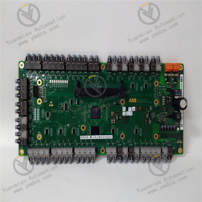
Yokogawa ANB11D‑225/BU2A is a dual‑redundant optical‑fiber ESB bus node unit originally manufactured by Yokogawa Electric, Japan. It is designed for the FIO (Field‑IO) distributed I/O architecture of CENTUM CS3000 and CENTUM VP DCS systems, and serves as a core optical‑fiber repeater communication module to replace conventional copper‑cable‑based ESB bus nodes.
Acting as an optical‑fiber communication hub between the DCS Field Control Unit (FCU) and distributed I/O modules, this unit integrates optical‑fiber signal transceiving, bus repeating, data forwarding, link redundancy, signal shaping and error‑correction functions to realize long‑distance, high‑immunity system‑bus data exchange. Compared with the traditional copper‑cable ANB10D bus module, this model adopts an opto‑electric conversion transmission architecture, which fundamentally eliminates the drawbacks of limited transmission distance and high electromagnetic susceptibility of copper cables, and greatly extends the allowable cabling length of field I/O buses in DCS systems.
Equipped with a dual‑redundant bus design for bumpless link switching and built upon an industrial‑grade reinforced hardware structure, the module is capable of long‑term 7×24‑hour continuous operation in petrochemical, chemical, power‑generation and other process‑industry environments. It is a standard core component for long‑distance I/O expansion, anti‑interference bus retrofitting and legacy copper‑cable bus upgrade projects of Yokogawa DCS systems.
2. Technical Parameters
2.1 Basic Specifications & Model Definition
‑ Product Model: ANB11D‑225/BU2A
‑ Product Series: Yokogawa ESB Optical‑Fiber Bus Node Unit Series
‑ Product Type: DCS optical‑fiber bus repeater, dual‑redundant communication node module
‑ Core Function: Optical‑fiber communication relay, bus‑link extension and data‑exchange management between FCU and FIO I/O modules for CENTUM VP / CS3000 DCS systems
‑ Model Configuration Explanation:
ANB11D – Dual‑redundant optical‑fiber ESB bus module
225 – Hardware configuration specification
BU2A – Standard bus interface and firmware revision
‑ Compatible Systems: Full‑range CENTUM CS3000, CENTUM VP DCS control systems
‑ Supported Architecture: FIO (Field IO) distributed field I/O architecture
‑ Mounting Method: Standard cabinet slot‑mounting, suitable for standardized layout of Yokogawa DCS cabinets
‑ Structural Feature: Compact modular design with lightweight body, saving cabinet space for dense cabinet layouts
2.2 Bus Communication & Transmission Parameters
‑ Bus Protocol: Natively compatible with Yokogawa proprietary high‑speed ESB (Enterprise Service Bus) protocol with full protocol matching
‑ Transmission Medium: Industrial optical‑fiber transmission; free of conductive interference with superior electrical isolation performance
‑ Transmission Distance: Supports long‑distance bus extension, breaking the transmission‑distance limit of copper‑cable ESB buses and meeting cross‑regional I/O layout requirements for large‑scale plant sites
‑ Transmission Speed: Compliant with standard high‑speed ESB bus rate; ultra‑low data‑forwarding latency and near‑zero frame‑loss ratio to guarantee real‑time I/O data interaction
‑ Redundancy Architecture: Two independent optical‑fiber communication links; primary‑standby hot‑standby monitoring and automatic bumpless switch‑over upon link failure
‑ Signal Processing: Built‑in opto‑electric conversion, waveform shaping, data verification and re‑transmission‑on‑error mechanisms to ensure accurate and reliable data over long‑distance transmission
2.3 Electrical & Operating Parameters
‑ Supply Voltage: Standard DC24 V industrial power supply, compatible with dedicated DCS power‑supply systems and tolerant of normal voltage fluctuations and transient surges
‑ Operating Power Consumption: Low‑power hardware design with low heat generation under continuous full‑load operation; no risk of overheating shutdown or communication interruption
‑ Operating Modes: Multi‑mode support for bus repeating, signal amplification and link extension, adapting to diverse field I/O networking schemes
‑ Link Monitoring: Real‑time self‑diagnosis of optical‑fiber link status, signal strength and communication quality, with immediate alarm upon anomalies
‑ System Interoperability: Seamless connection with FCU master controllers and all types of analog / digital I/O modules for synchronous system‑wide data exchange
2.4 Environmental & Protection Specifications
‑ Operating Temperature: ‑20 ℃ ~ +60 ℃ wide industrial temperature range, suitable for long‑term operation in hot control‑rooms and enclosed cabinet environments
‑ Storage Temperature: ‑40 ℃ ~ +70 ℃, satisfying requirements for long‑distance transportation and prolonged idle‑state storage
‑ Operating Humidity: 5 %‑95 % RH non‑condensing; resistant to humid, dusty and lightly‑oily industrial environments
‑ Anti‑interference Performance: Optical‑fiber transmission eliminates electromagnetic coupling interference, providing full immunity to strong EMI noise generated by variable‑frequency drives and high‑power equipment
‑ Vibration & Shock Resistance: Industrially‑reinforced modular construction tolerates long‑term cabinet vibration and equipment start‑stop shocks, preventing loose connectors and link faults
‑ Operational Reliability: Fully‑solidified hardware with no mechanically wearable parts; stable 7×24‑hour continuous operation without performance degradation
3. Product Functions and Core Advantages
3.1 Core Product Functions
Long‑distance optical‑fiber bus relay and extension
By replacing copper‑cable transmission with opto‑electric conversion technology, the unit effectively extends the ESB bus transmission distance of the DCS system. It resolves cabling‑distance bottlenecks for large‑scale process plants and scattered field I/O points, supports wide‑area cross‑regional I/O networking, and fits distributed automatic‑control architectures for large petrochemical and chemical complexes.
Bumpless switch‑over for dual‑redundant links
Two independent optical‑fiber communication links run in hot‑standby mode under normal conditions. Upon single‑link failure, optical‑fiber damage or signal attenuation, automatic bumpless switch‑over is executed without interrupting data transmission or affecting control logic, thus eliminating risks of system off‑line and loss‑of‑I/O caused by single‑point link failure.
Signal shaping and data error correction
Dedicated on‑board bus‑signal‑processing algorithms amplify attenuated long‑distance signals while performing data validation, bad‑frame rejection and lost‑data re‑transmission. This avoids data distortion, signal fluctuation and abnormal commands induced by long‑haul transmission and ensures precise, stable DCS data exchange.
End‑to‑end link monitoring and alarm
Real‑time monitoring of optical‑fiber continuity, signal strength, communication latency and bus load. Fault information including fiber breakage, connector contamination and signal attenuation is indicated via front‑panel LEDs and uploaded to the host system for fast fault location and maintenance response.
Seamless system compatibility and data forwarding
Natively compatible with the full Yokogawa CENTUM product family, the module receives, parses and forwards bus data between FCU controllers and all FIO I/O modules without additional protocol‑conversion hardware, achieving real‑time data linkage between the control host and field I/O devices.
Bus isolation and anti‑interference protection
Optical‑fiber transmission provides complete electrical isolation, blocking strong field electromagnetic interference, ground‑potential differences and surge noise from propagating into the master controller via the bus. This protects core DCS hardware and improves the overall noise immunity of the automation system.
3.2 Core Product Advantages
Optical‑fiber transmission with superior anti‑interference performance
Different from conventional copper‑cable bus modules, opto‑electrically‑isolated transmission fundamentally eliminates industrial electromagnetic interference and ground‑loop noise, resolving common DCS faults such as signal drift, intermittent communication drop‑outs and abnormal data readings in high‑noise industrial environments.
Extended transmission range and flexible networking
Removing the copper‑cable ESB distance restriction enables wide‑coverage distributed I/O layouts for large‑scale plants and remotely‑located field measuring points, reducing requirements for intermediate repeater cabinets and lowering system‑architecture and cabling costs.
Native system compatibility, risk‑free retrofitting
Purpose‑built for Yokogawa CS3000 and VP systems with fully‑matched protocol, firmware and hardware interfaces. Legacy ANB10D copper‑cable bus modules can be directly replaced with no modification to system programs, control logic or cabinet wiring, delivering convenient upgrade work with zero compatibility risk.
Dual‑redundant hot‑standby architecture for maximum reliability
The dual‑independent‑link redundant design removes single‑point‑of‑failure risks. High stability for year‑round continuous operation satisfies the strict zero‑downtime requirements of continuous process industries.
Low‑latency high‑stability performance with excellent control accuracy
High‑speed bus forwarding combined with error‑correction mechanisms maintains ultra‑low latency and zero‑packet‑loss performance even over long distances, guaranteeing precise closed‑loop process control, interlock execution and parameter regulation with no control lag.
Industrial‑grade durability and low maintenance costs
All‑solid‑state hardware with no consumable mechanical components. Optical‑fiber connectors feature high stability and ageing resistance. No parameter drift or performance decay occurs during long‑term service. Only routine visual inspection is required, greatly reducing system maintenance and troubleshooting workload.
4. Typical Application Scenarios
‑ Petrochemical Industry: Long‑distance distributed I/O bus extension and anti‑interference communication retrofits for large refining and chemical complexes
‑ Power‑generation Industry: DCS bus upgrades for thermal‑power, cogeneration and photovoltaic power stations to resolve high‑field‑noise and long‑cabling‑distance issues
‑ Oil & Gas Industry: Optical‑fiber communication extension and bus redundancy modification for remote field I/O nodes at oilfields, gas fields and long‑distance pipelines
‑ Fine‑Chemical & Pharmaceutical Industry: Long‑range DCS bus networking and communication‑stability optimization for clean‑rooms and distributed production facilities
‑ Water‑treatment Industry: Optical‑fiber DCS bus deployment and noise‑immunity upgrades for scattered measuring points in large‑scale industrial‑water‑treatment and municipal‑water‑supply plants
‑ Legacy‑System Retrofit Projects: Replacement of ageing ANB10D copper‑cable modules, bus anti‑interference upgrades and I/O‑network expansion for existing Yokogawa CS3000 / VP installations
5. Installation, Commissioning and Maintenance Guidelines
Before installation, fully cut off the main power supply of the DCS cabinet and module power, remove dust and oil contamination inside the cabinet. Insert the module securely into its designated slot and fasten it to prevent loosening, poor connector contact and communication anomalies caused by cabinet vibration.
Lay industrial optical‑fiber cables strictly in accordance with engineering drawings. Insert and extract fiber connectors gently; avoid impacts, contamination and sharp bending. Route fiber cables separately away from high‑power electrical cables to prevent mechanical crushing damage.
Distinguish between the two redundant optical‑fiber links and connect them respectively to the primary and standby bus ports. Wrong‑link interconnection is strictly prohibited to ensure normal hot‑standby and fault‑switch‑over functionality.
Supply stable and clean DC24 V industrial power. Prevent module reboot, bus disconnection and abnormal data forwarding induced by voltage fluctuations, harmonic distortion or loose power connections, so as to guarantee 24‑hour stable online operation.
During initial commissioning, match the system firmware revision, complete bus‑communication configuration, dual‑link redundancy‑switch‑over testing and I/O‑data joint debugging. Simulate single‑link‑failure conditions to verify bumpless link switch‑over, accurate data transmission and correct alarm response.
During routine maintenance, periodically inspect module LED status, fiber‑connector cleanliness and link health. Monitor bus load, signal strength and communication logs via the host system to detect hidden faults such as optical‑signal attenuation and connector ageing at an early stage.
Regularly clean fiber connectors and module ports. Maintain good cabinet ventilation and dry, dust‑free conditions to prevent connector oxidation, moisture‑related communication degradation and premature hardware ageing.
Faulty units shall be replaced exclusively with an original Yokogawa ANB11D‑225/BU2A module. After replacement, restore all original system configurations and complete bus joint‑commissioning, redundancy testing and process‑loop trials to ensure that communication stability and data‑transmission accuracy remain fully consistent with pre‑replacement performance.