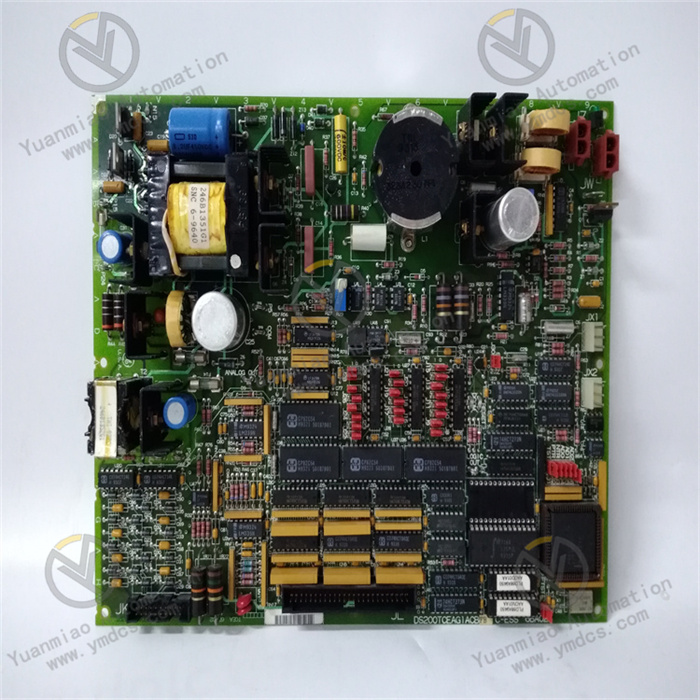
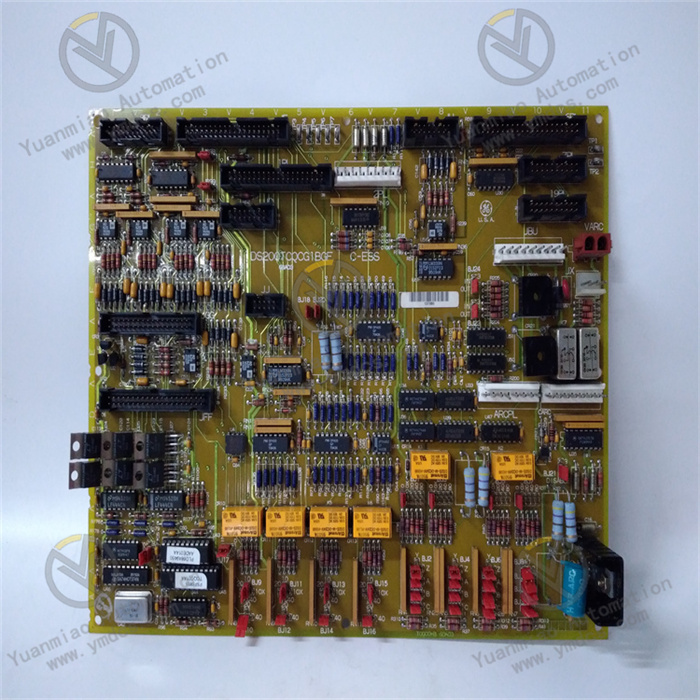
Description
ABB AO845 3BSE023676R1
I. Overview
ABB AO845 3BSE023676R1 is a high-performance analog output module, mainly designed to convert digital signals from control systems into standard analog signals, achieving precise control of industrial field actuators (such as control valves, frequency converters, servo drives, etc.). As a core executive layer component in the field of process control, this module features high reliability, high precision, and strong environmental adaptability. It is widely used in heavy industry scenarios including petrochemicals, electric power energy, metallurgy and building materials, and water treatment, providing reliable signal conversion and control support for the stable operation of industrial processes.
II. Product Features
Multi-channel Precision Output: Equipped with 4 independent analog output channels, each channel can be independently configured with output type and range. It supports mainstream standard analog signals such as 4-20mA, 0-20mA, and 0-10V, featuring high output precision and small linear error, which can meet the control requirements of different actuators.
Hot-swapping and Redundancy Design: Supports online hot-swapping operation. Module replacement does not require interrupting the operation of the entire control system, greatly improving system availability. Redundant deployment is supported under certain configurations, further enhancing system reliability and fault tolerance.
Comprehensive Self-diagnostic Function: Built-in high-precision fault detection circuit can monitor abnormal states such as channel output short circuit, overload, and signal drift in real time. Fault information is transmitted to the controller and upper monitoring system via the system bus, facilitating maintenance personnel to quickly locate and handle faults.
Strong Environmental Adaptability: The operating temperature range covers 0℃ to +60℃, and the storage temperature range is -40℃ to +85℃, capable of withstanding high and low temperature environments in industrial sites. It has good electromagnetic interference resistance, complying with relevant industrial EMC standards, ensuring stable signal output in complex electromagnetic environments.
Convenient Configuration and Debugging: Supports parameter configuration through the configuration software of the ABB Advant OCS system. Parameters such as output range, unit, and fault-safe value of each channel can be flexibly set. Signal simulation output can be performed through software during debugging, simplifying the debugging process.
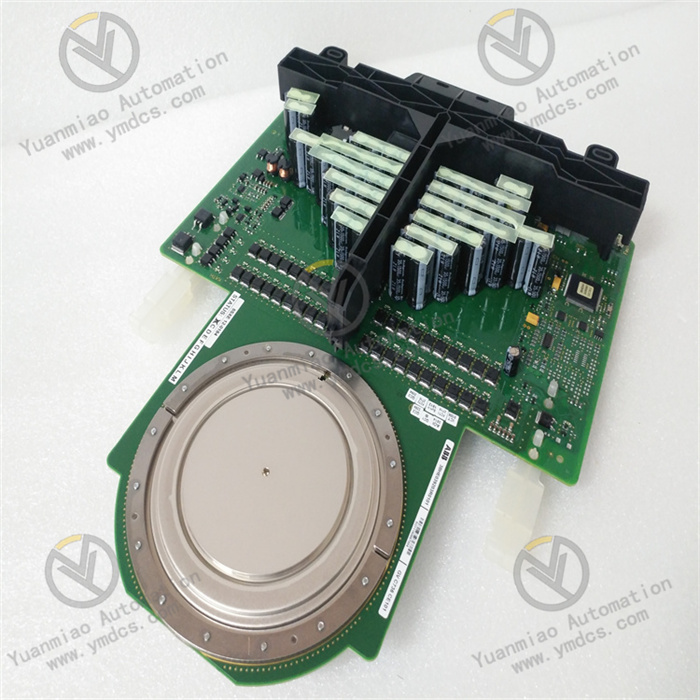
- Standardized Integration Design: Adopts rack-mount dimensions complying with industrial standards, which can seamlessly adapt to various controller racks of the ABB Advant OCS system. It works collaboratively with other modules in the system (such as AI modules, DI/DO modules) to build a complete process control system.
III. Technical Parameters
1. Core Basic Parameters
- Product Model: AO845
- Order Number: 3BSE023676R1
- Product Type: Analog Output Module
- System: ABB Advant OCS Process Control System
- Manufacturer: ABB
2. Output Performance Parameters
- Number of Channels: 4 independent analog output channels
- Supported Signal Types: 4-20mA, 0-20mA, 0-10V
- Output Accuracy: ±0.1% FS (Full Scale)
- Linear Error: ≤±0.05% FS
- Response Time: ≤10ms (from digital signal input to stable analog signal output)
- Load Capacity: Maximum load of 600Ω for current output; Minimum load of 1kΩ for voltage output
3. Power Supply and Environmental Parameters
- Supply Voltage: 24V DC (±10%)
- Power Consumption: Approximately 5W under normal operation, maximum power consumption not exceeding 8W
- Operating Temperature: 0℃ to +60℃
- Storage Temperature: -40℃ to +85℃
- Relative Humidity: 5% to 95% (non-condensing)
- Protection Class: IP20 (module itself, suitable for installation in control cabinets)
4. Physical and Interface Parameters
- Mounting Method: Standard rack-mount installation for ABB Advant OCS
- Dimensions: 130mm × 210mm × 80mm (Length × Width × Height, subject to actual product)
- Weight: Approximately 0.8kg
- Communication Interface: Communicates with the controller via the system backplane bus
- Terminal Type: Spring terminal, supporting connection of 1.5-2.5mm² wires
IV. Working Principle
The core working principle of the ABB AO845 3BSE023676R1 analog output module is "Digital Signal Reception - Signal Conversion - Analog Output - Status Monitoring". Through the built-in Digital-to-Analog (D/A) conversion chip and signal conditioning circuit, it realizes precise conversion of digital commands from the control system into analog signals recognizable by field actuators.
The specific working process is as follows: First, the module receives digital control signals from the ABB Advant OCS controller via the system backplane bus, which contain the target operating parameters of the actuators (such as numerical commands corresponding to valve opening and motor speed). Then, the built-in D/A conversion chip converts the digital signals into preliminary analog signals. After processing by the signal conditioning circuit (including amplification, filtering, voltage stabilization, etc.), the analog signals are calibrated to industrial-standard 4-20mA, 0-20mA or 0-10V signals. Finally, the stable analog signals are transmitted to the corresponding actuators through independent output channels, driving the actuators to operate according to the control commands.
V. Common Troubleshooting
1. No Output Signal Response / Zero Signal
Phenomenon: After the upper system sends a control command, there is no analog signal output from the corresponding channel of the module, or the output signal is always zero, and the actuator does not operate.
2. Output Signal Drift / Large Precision Deviation
Solutions: 1. Check the temperature inside the control cabinet. If it exceeds the working temperature range, install cooling fans or air conditioners to improve ventilation and heat dissipation conditions. 2. If the module has been in long-term operation (more than 5 years), contact ABB after-sales service for component testing and aging evaluation, and replace the module if necessary. 3. Verify the load resistance of the actuator, ensure that the load ≤ 600Ω for current output and load ≥ 1kΩ for voltage output. If the range is exceeded, install a signal isolator or matching resistor. 4. Re-calibrate the channels through the configuration software or special calibration tools, and update the calibration parameters. 5. Check whether there are strong electromagnetic interference sources such as frequency converters and high-power motors near the module. Keep the module at least 30cm away from the interference sources, or install shielding layers for the output wires and ensure single-point grounding.
3. Output Short Circuit / Overload Fault Alarm
4. Module Cannot Be Hot-swapped / No Response After Hot-swapping