Description
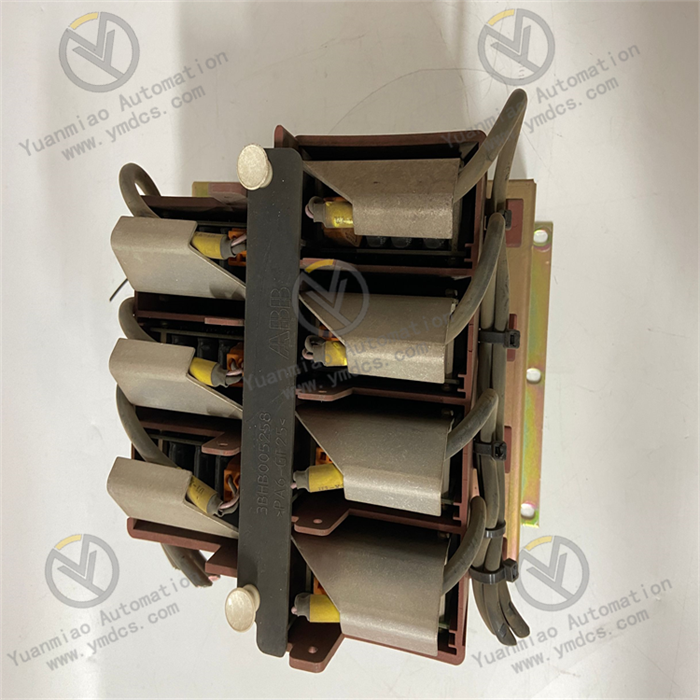
ABB 3BHE035301R1002 UNS0121A-Z,V1
ABB 3BHE035301R1002 UNS0121A-Z, V1 is a model in the UNITROL 1010 indirect excitation system, mainly used for voltage regulation of small and medium-sized synchronous generators and industrial machines
Functional Features
- Advanced Microprocessor Technology: Equipped with a 32-bit RISC processor running at 200MHz, enabling fast and accurate processing of various control tasks for high-performance excitation control.
- Dual-Channel Support: Built-in dual channels for load distribution in parallel operation units, optimizing performance in multi-unit setups and ensuring balanced load sharing.
- Rotating Diode Monitoring: Monitors rotating diodes to promptly detect faults, enhancing system reliability and stability.
- Automatic Synchronization Function: Rapidly and accurately synchronizes generators with the power grid or other generators, reducing inrush and losses during paralleling.
- Multiple Communication Options: Provides rich communication interfaces (e.g., RS232, RS485, Ethernet) supporting various integrated communication protocols for seamless data interaction and system integration with other devices.
- Wide Operating Temperature Range: Operates reliably in temperatures from -25°C to +70°C, adapting to harsh industrial environments.
- High Reliability and Efficiency: Rigorously tested and validated, using high-quality components and advanced design principles to minimize maintenance costs and downtime.
Working Principle
- Data Acquisition and Input Processing: Collects electrical parameters (e.g., terminal voltage, stator current) via analog input interfaces and non-electrical parameters (e.g., temperature, rotational speed) while receiving switch status signals through digital input interfaces. Analog signals are filtered, amplified, and converted to digital signals by an ADC for processing by the microprocessor.
- Control Algorithms and Logical Operations: Employs PID control algorithms or advanced strategies (e.g., adaptive control, predictive control) based on the microprocessor to calculate required excitation current adjustments from the deviation between set voltage references and actual measurements, ensuring precise voltage regulation. In multi-generator parallel setups, it balances reactive power distribution by adjusting excitation current to maintain grid stability. Built-in protection algorithms (overvoltage, undervoltage, overcurrent, overheating) trigger rapid protective actions upon detecting anomalies.
- Output Control and Execution: The microprocessor outputs switch signals (e.g., thyristor trigger pulses) via digital output interfaces to control the on/off of excitation power units and sends analog signals via analog output interfaces to adjust excitation regulator setpoints, enabling precise control of generator excitation current.
- Communication and System Integration: Supports communication protocols (e.g., Modbus TCP, Ethernet/IP, PROFINET) via RS232, RS485, and Ethernet interfaces to exchange data with host computers (e.g., PLCs, HMIs) for remote parameter setting, real-time status monitoring, fault data upload, and historical record query. Some models support dual Ethernet port redundancy to enhance communication reliability and avoid single-point failures.
Technical Parameters
- Input Voltage: 120V AC
- Power Supply Voltage: 24V DC
- Processor: 32-bit RISC processor, 200MHz
- I/O Points: Up to 256 points
- Communication Interfaces: RS232, RS485, Ethernet
- Power Consumption: 20W
- Operating Temperature: -25°C to +70°C
- Storage Temperature: -40°C to +85°C
- Protection Rating: IP67
Additionally, this model weighs 2.9 kg (net) and 3.3 kg (shipping weight), suitable for applications with 100kVA to 80MVA synchronous motors. Its static and indirect excitation system handles current ranges from 20 to 12,000A.
Common Faults and Solutions
1. Communication Failures
- Symptoms:
- Unable to communicate with host computers (e.g., PLCs, HMIs) or other devices.
- Interrupted data transmission, packet loss, or error codes (e.g., Modbus timeouts).
- Communication indicator lights (e.g., LINK/ACT) off or flashing abnormally.
- Possible Causes:
- Physical Connection Issues: Loose, damaged, or incorrectly wired communication cables (e.g., missing ground connection per protocol requirements); oxidized or poor interface terminal contacts.
- Parameter Configuration Errors: Mismatched baud rate, data bits, parity, or station address; incorrect protocol selection (e.g., Modbus RTU instead of Modbus TCP).
- Electromagnetic Interference: Communication cables near high-power lines or high-frequency equipment causing signal distortion.
- Hardware/Firmware Faults: Damaged communication chips, incompatible firmware versions, or corrupted firmware.
- Solutions:
- Check Physical Connections: Replug cables, test continuity with a multimeter, and replace damaged cables; clean terminals and ensure secure connections, replacing terminal blocks if needed.
- Verify Parameter Configuration: Confirm module communication parameters (e.g., 115200 baud, 8 data bits, no parity) match the host system per the manual; reset to default settings and retest parameters incrementally.
- Anti-Interference Measures: Use shielded twisted-pair cables, route away from power cables, or add signal filters; ensure proper grounding for the module and devices to reduce ground loop interference.
- Firmware Upgrade or Hardware Replacement: Update firmware to the latest version via ABB tools (e.g., PC Tools) or restore factory firmware; contact ABB support to replace the module if the communication chip is faulty.
2. Power Supply Failures
- Symptoms:
- Module power indicator (e.g., PWR) off and unresponsive.
- Flashing power indicator with frequent restarts or freezes.
- Possible Causes:
- Abnormal External Power Supply: Input voltage outside the rated range (e.g., nominal 12V DC but actual <10V or >15V); faulty power adapters, damaged power cables, or loose plugs.
- Internal Power Module Faults: Aging components (e.g., bulging filter capacitors, burnt resistors); failed power redundancy (if applicable).
- Solutions:
- Test External Power Supply: Measure input voltage with a multimeter to ensure it meets specifications (e.g., +12V DC ±10%); replace power adapters or cables with spares to rule out external issues.
- Inspect Internal Power Supply: Power off and check for visible damage (e.g., leaking capacitors) in the module’s power section; contact maintenance or replace the module if damaged. For redundant models, verify the redundant power module’s functionality.

3. Input/Output (I/O) Failures
- Symptoms:
- No analog input (AI) signal or erratic values (e.g., 4-20mA input shows 0 or out of range).
- Digital output (DO) fails to trigger or mismatches commands (e.g., relays not activating).
- Abnormal I/O channel indicator lights (e.g., DI channel light off with input signal).
- Possible Causes:
- Signal Source or Load Issues: Faulty sensors (no AI output), overloaded loads (DO current exceeding ratings); unshielded or non-differential AI signals prone to interference.
- Wiring Errors: Reversed signal polarities, high common-mode voltage (e.g., ungrounded AI channels); missing freewheeling diodes for inductive DO loads, causing back EMF damage.
- Channel Damage: Long-term overloading, short circuits, or surge impacts burning I/O chips.
- Solutions:
- Test Signal Sources and Loads: Directly measure sensor outputs (e.g., at AI input terminals) with a multimeter; manually test DO channels (e.g., force output via module diagnostics) to identify whether the fault lies with the module or load.
- Check Wiring and Protection: Reverify connections against schematics, ensuring differential AI inputs and correct DO load circuits; add freewheeling diodes or surge protectors for inductive loads to prevent voltage spikes.
- Replace Channels or Module: Switch to backup channels (if available) for single-channel faults; return the module for repair or replace it if multiple channels fail, indicating internal circuit damage.
4. Overheating or Environmental Failures
- Symptoms:
- Excessive module temperature, overheat indicator activation, or automatic shutdown.
- Unusual noises (e.g., fan failure), blocked cooling vents causing poor airflow.
- Possible Causes:
- Exceeding Temperature Limits: Operating temperature above the rated range (e.g., nominal -40°C~70°C but actual 80°C).
- Inadequate Cooling: Poor ventilation around the module, dust/clogged cooling vents; failed internal fans (if present) or detached heat sinks.
- Solutions:
- Improve Environmental Conditions: Install the module in a well-ventilated cabinet, maintaining spacing (e.g., ≥5cm) from other devices; use air conditioning or fans to cool the cabinet and avoid direct sunlight.
- Clean and Maintain: Regularly blow out dust from the module and vents with compressed air; check fan operation and replace or repair fans if they stop rotating.