Description
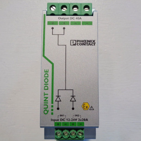
Phoenix QUINT-DIODE/12-24DC/2x20/1x40
I. Product Overview
- Model: QUINT-DIODE/12-24DC/2x20/1x40
- Version: Standard Version
- Global Part Number: 2320157
- Product Series: Phoenix Contact QUINT Series Industrial Diode Redundancy Module
- Product Category: DC-DC Diode Redundancy Module (for parallel redundancy / capacity expansion of power supplies to achieve bumpless switching)
- Country of Origin: Germany
Core Functions
This device is a core diode redundancy module in the Phoenix Contact QUINT series, designed for high-reliability redundant power supply in industrial power systems.It mainly provides isolation, redundant switching and load distribution after paralleling the outputs of two identical power supplies, effectively improving the operational reliability of the entire power supply system.
Built with two high-capacity diodes, it supports flexible switching between two operating modes:
- Redundancy mode: Connect two 20 A rated power supplies to achieve bumpless switching. If one power supply fails or mains power is interrupted, the other automatically takes over the full load to prevent system shutdown.
- Capacity expansion mode: Parallel two power supplies to provide a single 40 A rated output to meet high-load power demands.
The module features a low voltage drop of 0.5 V and efficiency of over 97%.It has built-in varistors for transient surge protection and supports reverse polarity protection (withstand voltage < 60 V), requiring no additional protective components.It uses DIN rail clip mounting, compatible with standard industrial control cabinet layouts, and can seamlessly integrate with QUINT series power supplies.It supports series connection of DC-OK relay contacts for redundant status monitoring, meeting continuous power supply requirements in harsh industrial environments.
Application Scenarios
Widely used in fields with extremely high power supply reliability requirements, such as automotive manufacturing, metallurgy, petrochemical, power, rail transit, water treatment and automated production lines.Suitable for QUINT series and equivalent industrial DC power supplies, used in redundant power supply systems for critical loads including PLC, DCS, remote I/O, HMI, servo drives and solenoid valves.
Especially ideal for critical control systems requiring 24/7 continuous operation, such as emergency stop circuits, safety PLC systems, data center UPS outputs, offshore platform power supply, and potentially explosive areas (compliant with EN 50021 for Zone 2 hazardous environments).It enables power supply parallel redundancy or capacity expansion to ensure uninterrupted system power if one power supply fails, greatly improving the availability and stability of industrial automation systems.

II. Technical Specifications
| Parameter Category | Details |
|---|---|
| Electrical Specifications | Input/output voltage: Rated 12–24 VDC, operating range 10–30 VDCRated current: Redundancy mode 2×20 A (-25℃~60℃); Expansion mode 1×40 A (-25℃~60℃)Max. current: 2×30 A (-25℃~40℃); 1×60 A (-25℃~40℃)Voltage drop: ≤ 0.5 V between input and outputProtection: Built-in varistor for transient surge protection; reverse polarity protection (withstand < 60 V)Efficiency: ≥ 97% at rated loadPower loss: Max. 10 W at rated load (20 A output)Monitoring: Supports series connection of DC-OK relay contacts for redundant status monitoring |
| Physical Specifications | Mounting: Standard NS 35 DIN rail, compact size, matching QUINT series power supply layoutNet weight: approx. 0.5 kg (subject to original factory specifications)Protection degree: IP20 (must be installed in a control cabinet)Mounting method: DIN 35 rail clip mounting, no auxiliary screws required; exposed terminals for easy wiring and maintenance |
| Environmental Adaptability | Operating temperature: -25℃ to +70℃ (derated by 2.5%/K from 60℃ to 70℃)Storage temperature: -40℃ to +85℃Relative humidity: 5%–95% (non-condensing)Immunity / Surge: Complies with industrial EMC standards, built-in transient surge suppression devicesCompliance: EN 50021 for potentially explosive areas (Zone 2); RoHS compliant |
III. Installation and Maintenance Guide
Pre-installation Requirements
- Anti-static: Wear a grounded anti-static wristband before operation. Do not touch terminals or internal electronic components with bare hands. Keep the module in an anti-static bag until installation to avoid electrostatic damage.
- Environment: Install in a dust-free, non-condensing, well-ventilated control cabinet, away from strong interference/heat sources such as inverters, high-voltage cables and high-power thyristors. Equip the cabinet with fans or air conditioning to maintain -25℃~+70℃. Prevent direct contact with dust, oil mist or condensation, especially in Zone 2 hazardous areas.
- Wiring rules: Strictly distinguish power input, output and ground terminals according to markings. Use two identical power supplies with consistent output voltages. Route power and signal cables in separate ducts; ground terminals must be securely connected to the system ground busbar. In redundancy mode, connect each power supply to the corresponding module input; in expansion mode, wire correctly. Reverse connection or short circuit is prohibited. Wire DC-OK relay contacts in series per manual to ensure proper monitoring.
- Parameter setup: After installation, confirm the operating mode (redundancy/expansion) matches the wiring. Check output voltage consistency of the two parallel power supplies. Verify no short circuits or reversed wiring before power-on. Test redundant switching to ensure bumpless transfer under fault conditions.
Routine Inspection
- Indicator lights: Observe the module status indicator (if equipped); steady on during normal operation, abnormal in case of fault (per factory labeling). Monitor DC-OK signals to confirm normal redundant system status without alarms.
- Temperature and ventilation: Ensure the module housing is not abnormally hot. Keep cabinet filters clean and fans quiet. Maintain unobstructed heat dissipation, especially under high load, to avoid exceeding derating temperature limits.
- Wiring and terminals: Inspect input/output terminals and ground screws for looseness, oxidation or burning. Check cables for aging or cracking; ensure tight connections and even current distribution between the two power supplies.
- Operating parameters: Measure input/output voltage with a multimeter to confirm voltage drop within 0.5 V. Monitor load current: in redundancy mode, keep each power supply within rated current; in expansion mode, total load ≤ 40 A to avoid overload.
Periodic Maintenance
- Every 6 months: Clean cabinet filters and dust on the module; retighten all terminals; test redundant switching by simulating one power supply fault to verify bumpless takeover; check DC-OK monitoring function.
- Annually: Measure voltage drop, efficiency and insulation performance with professional instruments; inspect internal diodes for aging or damage; back up redundant system configuration; verify grounding reliability and optimize wiring; establish maintenance records.
- Every 2 years: Fully test surge suppression and reverse polarity protection; assess module aging and diode conduction performance; evaluate replacement cycles for units in high-dust, corrosive or hazardous environments; confirm compatibility with parallel power supplies and perform firmware updates if supported and needed.
IV. Common Faults and Troubleshooting
| Fault Symptom | Possible Causes | Troubleshooting & Solutions |
|---|---|---|
| No module output, load power failure | 1. Both parallel power supplies faulty or without input2. Reversed, shorted or loose wiring3. Internal diode damage4. Reverse polarity protection triggered | 1. Check input and status of both power supplies and restore power2. Verify wiring, retighten terminals, eliminate short circuits and reversed connections3. Power off, test diode continuity; replace module if defective4. Check polarity, correct wiring and restart |
| Abnormal redundant switching, load shutdown on fault | 1. Mismatched output voltages of two power supplies2. Incorrect operating mode configuration3. Wrong DC-OK monitoring wiring4. Internal switching circuit failure | 1. Adjust output voltages for consistency2. Confirm mode (redundancy/expansion) matches wiring and reconfigure3. Check and correct DC-OK series wiring4. Return module for factory inspection and repair if other issues are ruled out |
| Excessive module heating and power loss | 1. High ambient temperature or poor ventilation2. Load current exceeds rating3. Abnormally increased voltage drop4. Internal diode aging | 1. Improve cabinet cooling and clear heat ducts2. Reduce load to within rated current3. Measure voltage drop; check wiring or replace module if >0.5 V4. Test diodes and replace module if aged |
| Abnormal or false DC-OK alarm | 1. Loose or incorrect DC-OK wiring2. DC-OK signal fault of parallel power supplies3. Internal monitoring circuit failure | 1. Tighten DC-OK wiring and verify connection per manual2. Check DC-OK signals of both power supplies3. Return module for factory repair if other causes are eliminated |