Description
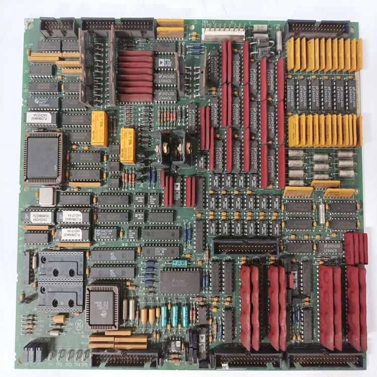
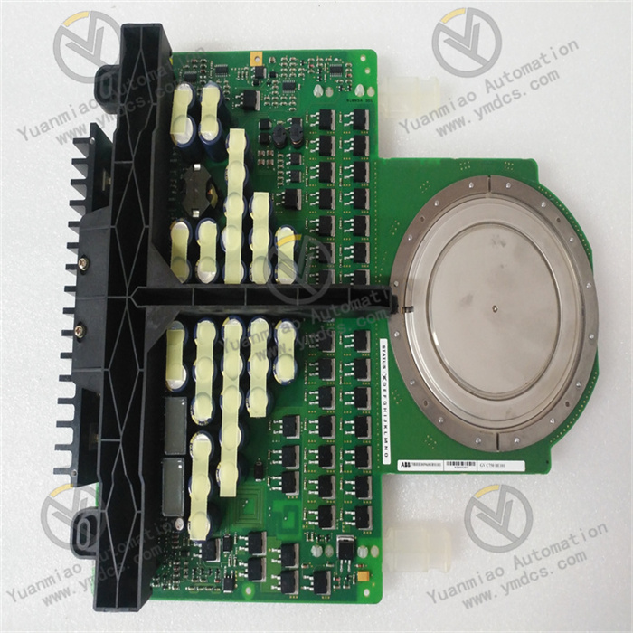
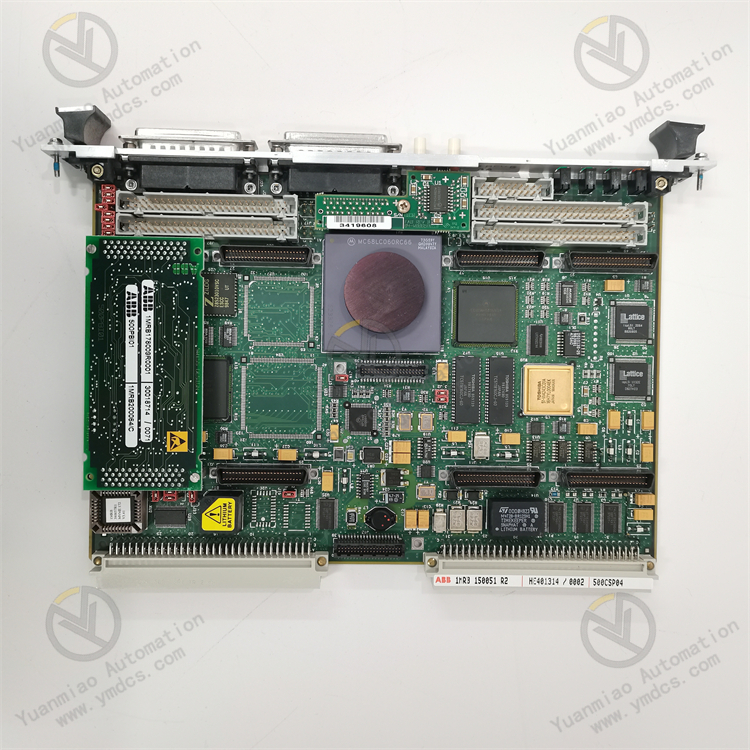
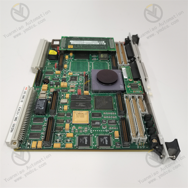
ABB 500CSP04 HE401314/0002 1MRB150051R2
The ABB DCS 500 is a thyristor power converter used in DC drive systems, with a current range of 25 - 5150A. This series has the following characteristics:
Performance and Reliability
Leveraging ABB's rich experience in DC drives, it adopts high-quality components and the latest production technologies to ensure reliable operation, meeting the performance requirements and flexibility of industrial or commercial applications.
Standard Functions
It includes design and debugging tools, monitoring functions, data bus communication, and human-machine interfaces. Additionally, there are over 300 additional function blocks programmable in Windows, a graphical application designer, and plain text display.
Operational Features
Equipped with a detachable control panel, it provides external digital field power supply and can be connected to programmable controllers and automation systems. It features Windows-based programming tools (GAD) and debugging/maintenance tools (CMT), as well as externally isolated I/O boards. These features enable users to conveniently control, monitor, and program the drive, and flexibly modify drive applications.
Technical Parameters
ABB DCS 500 Series Thyristor Power Converter
- Rated Voltage: 220 - 1000V ± 10% AC
- Input Voltage: Three-phase AC, rated frequency 50/60Hz, dynamic frequency range 45 - 65Hz
- DC Current: 25 - 5150A, short-term overload capacity of 150% for 1 minute
- Operating Temperature: +5°C - +40°C
- Storage Temperature: -40°C - +55°C
- Relative Humidity: 95% non-condensing
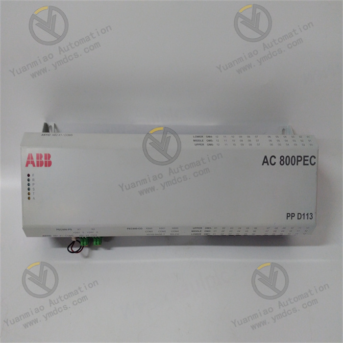
ABB AC500 Series PLC
- CPU Display and Interfaces: With an LCD display, a set of operation keys, an SD card expansion slot, and two integrated serial communication ports. In addition to the integrated communication interfaces, each CPU can expand up to 4 communication interfaces, including bus interfaces such as Profibus DP-V1, DeviceNet, CANopen, and Ethernet.
- Communication Distance: 500 meters without repeaters, up to 2000 meters with repeaters
- Input/Output Modules: Two types: analog and digital. Each I/O module can be directly plugged into the terminal block. The CPU local station and distributed sub-stations expanded via FBP can support a maximum of 7 I/O modules. Terminal blocks are available in two voltage levels (24V DC and 230V AC) with screw or spring wiring options.
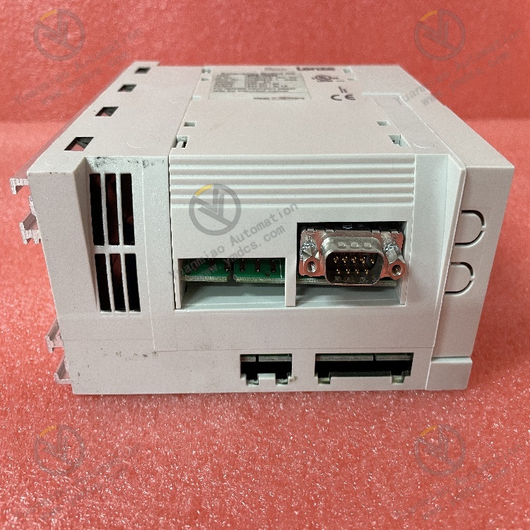
ABB ACS500 Frequency Inverter
- Analog Output Channels: Adjustable amplitude, zero adjustment, etc.
- Frequency-Related Parameters: Start-up initial operating frequency, maximum operating frequency, frequency skip range, etc.
- Overload-Related Parameters: Rated overload multiple, rated overload detection current, etc.
- Voltage-Related Parameters: Output voltage boost coefficient, inverter output knee voltage, rated input voltage, etc.
- Time-Related Parameters: Frequency rise/fall time limits, acceleration time at frequency rise points, deceleration time at frequency fall points, etc.
Working Principles
ABB Frequency Inverter
First, the AC voltage is converted into a smooth DC voltage through rectification and filtering, then the DC voltage is converted into an adjustable AC voltage (in frequency and voltage) by an inverter device. Motor speed is controlled by changing the voltage and frequency. For example, the ABB ACS800 series inverter uses Direct Torque Control (DTC) technology, which can measure the motor's actual speed and status in milliseconds, start instantly in any state, and provide full motor torque without speed feedback at zero speed.
ABB Positioner
The rotating actuator is equipped with a 100° cam, which is scanned by an inductive non-contact sensor to convert the rotation angle into an electrical signal. The position sensor, CPU, and cam form a regulating unit.
The pneumatic output module consists of an analog 3-position 3-way valve and a pilot stage, which converts electrical signals into pressure signals via a system of nozzles, flappers, and coil magnets. The main pressure control stage has two air outlet/inlet positions and a middle position; once the set point is reached, the valve switches to the middle position to avoid air loss. The microprocessor calculates the control deviation and outputs correction signals to the pneumatic unit, while the electrical unit reads the 4-20mA input loop set point and converts the position sensor signal via an A/D converter to control the process variable.
The pneumatic output module consists of an analog 3-position 3-way valve and a pilot stage, which converts electrical signals into pressure signals via a system of nozzles, flappers, and coil magnets. The main pressure control stage has two air outlet/inlet positions and a middle position; once the set point is reached, the valve switches to the middle position to avoid air loss. The microprocessor calculates the control deviation and outputs correction signals to the pneumatic unit, while the electrical unit reads the 4-20mA input loop set point and converts the position sensor signal via an A/D converter to control the process variable.
ABB AC500 PLC
By reading input signals, processing them according to user-programmed logic, and outputting corresponding control commands to drive actuators, it achieves precise control of mechanical equipment. The Central Processing Unit (CPU), as the "brain" of the PLC, executes programs and manages all input/output activities. Analog Input/Output (AI/AO) modules handle continuous signals such as temperature and pressure.
Common Faults and Solutions
Overcurrent Fault
- Causes: Output current exceeds the software-set overcurrent trip limit, possibly due to load short circuit, mechanical jamming, inverter module damage, or improper parameter settings (e.g., too short acceleration/deceleration times).
- Solutions: Check for motor load short circuits or mechanical transmission jams, adjust parameter settings, and verify the accuracy of encoder data (if used).
Undervoltage Fault
- Causes: Insufficient DC voltage in the DC loop, possibly due to grid phase loss, blown fuses, internal rectifier bridge faults, or capacitor leakage.
- Solutions: Check main power supply, especially the contactor control circuit at the inverter input. If the undervoltage fault cannot be reset, inspect DC capacitors for leakage. Wait for capacitors to discharge (about 5 minutes) before restarting after power-off.
Overheating Fault
- Causes: Excessive internal temperature in the inverter, possibly due to faulty cooling fans, high ambient temperature, or poor internal heat dissipation.
- Solutions: Check cooling fan operation, clean internal dust, and ensure good heat dissipation. For ACS500 series inverters, specifically inspect deflection capacitors for faults.
Driver Thick Film Damage Fault
- Causes: Damage to the driver thick film (which includes drive circuits, short-circuit detection, and IGBT module detection) due to overcurrent, overheating, or long-term high-load operation.
- Solutions: If no spare parts are available, repair the thick film. Note that components are soldered on a ceramic substrate with fast heat dissipation; avoid prolonged heating during repair to prevent damage.
Communication Fault
- Causes: Poor communication line connections, incorrect protocol settings, or interference.
- Solutions: Check for secure and undamaged communication lines, confirm protocol settings match other devices, and implement anti-interference measures (e.g., shielded cables, filters) to avoid interference from high-power equipment.