Description
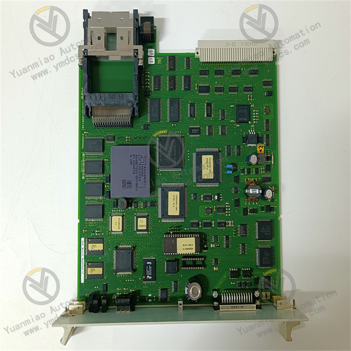
GE IS200TTURH1CCC
Functional Features
- Strong Application Scenario Specificity: Primarily used in the management or control systems of wind, gas, and steam turbines. As a key component of the Mark VI turbine control system, it provides support for turbine control and protection.
- Support for Multiple Application Modes: Capable of supporting simplex and triple modular redundancy (TMR) applications, allowing configuration based on different system reliability requirements to enhance system stability and fault tolerance.
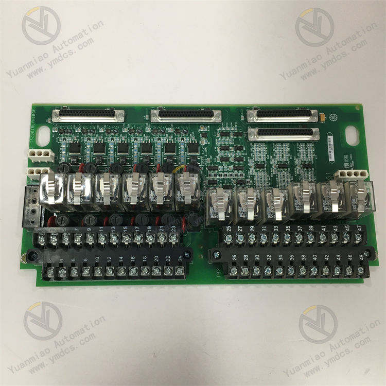
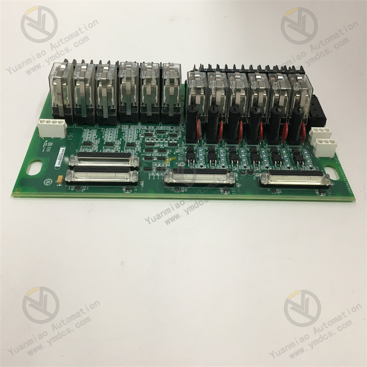
- Reliable Connectivity: Equipped with three 37-pin female ports and three 37-pin male connectors for connecting to the Trip Terminal (TRPG) board, enabling reliable communication and data transmission with other system components.
Technical Parameters
- Power Supply Voltage: 125 VDC.
- I/O Channels: 16 input channels and 16 output channels, meeting the needs of multi-signal input and control command output.
- Operating Temperature: -40°C ~ +70°C, adapting to a wide temperature range and ensuring stable operation in harsh industrial environments.
- Communication Protocols: Supports Ethernet and serial communication protocols, facilitating data interaction and remote monitoring with other devices or systems.
- Dimensions: Standard module size for easy installation and integration into various industrial control system cabinets.
Working Principle
- Signal Acquisition and Transmission: Collects sensor signals (such as temperature, pressure, and rotational speed) from turbines and related equipment through various input interfaces. These analog or digital signals are conditioned and converted, then transmitted to other parts of the control system for processing.
- Control Command Output: Receives control commands from the control system and transmits signals to corresponding actuators (such as valves and motors) via output interfaces to achieve precise control of turbine parameters (e.g., rotational speed, power), ensuring stable operation under different working conditions.
- Communication Interaction: Uses Ethernet or serial communication protocols to communicate with the host monitoring system or other related devices, uploading real-time operating status information of the turbine while receiving control commands and parameter settings from the host to enable remote monitoring and management.
Common Faults and Solutions
- Communication Faults: May be caused by damaged communication cables, incorrect communication parameter settings, or faulty interface chips. Solutions include replacing cables, checking wiring, reconfiguring communication parameters (e.g., baud rate, address), and replacing modules or repairing interface circuits if chip faults are confirmed.
- Abnormal Input Signals: Causes may include sensor failures, electromagnetic interference due to poor cable shielding, or loose interface connections. Solutions include calibrating or replacing sensors, checking grounding of cable shielding layers, and re-plugging terminals to ensure secure connections.
- No Output Response: May result from damaged output channels, actuator power failures, or control logic errors. Solutions include testing output channels, checking actuator power supplies, and debugging control programs to confirm command correctness.
Operation Guide
- Installation Requirements: Take precautions against electrostatic damage during installation, such as using anti-static packaging and wearing anti-static wrist straps. Install in a dry, non-corrosive, and low-electromagnetic-interference location, vertically on a standard rail or cabinet panel, ensuring sufficient cooling space above and below the module.
- Wiring Steps: Carefully distinguish between power wiring, signal wiring, and communication wiring. For power wiring, confirm the input voltage type, use flame-retardant cables, and ensure reliable grounding. For signal wiring, use shielded twisted-pair cables and correctly connect input/output terminals, paying attention to differences between analog and digital signals. For communication wiring, connect corresponding pins according to protocol requirements and install terminating resistors as needed.
- Parameter Configuration: Configure via GE proprietary software or third-party tools, including setting communication parameters (e.g., baud rate, data bits, stop bits, slave address), defining input/output mapping (e.g., channel-to-physical signal type), and configuring control parameters (e.g., PID coefficients, alarm thresholds, safety interlock logic).
- Debugging and Maintenance: Before powering up, carefully check wiring, power voltage, and terminal screw tightness. Perform functional tests, such as applying standard signals to sensors to verify software readings for analog inputs and forcing outputs via software to observe actuator movements and indicator status for digital outputs. In daily maintenance, regularly clean the module, check cable connections, record operation logs, analyze abnormal data, and periodically power on spare modules for testing.