Description
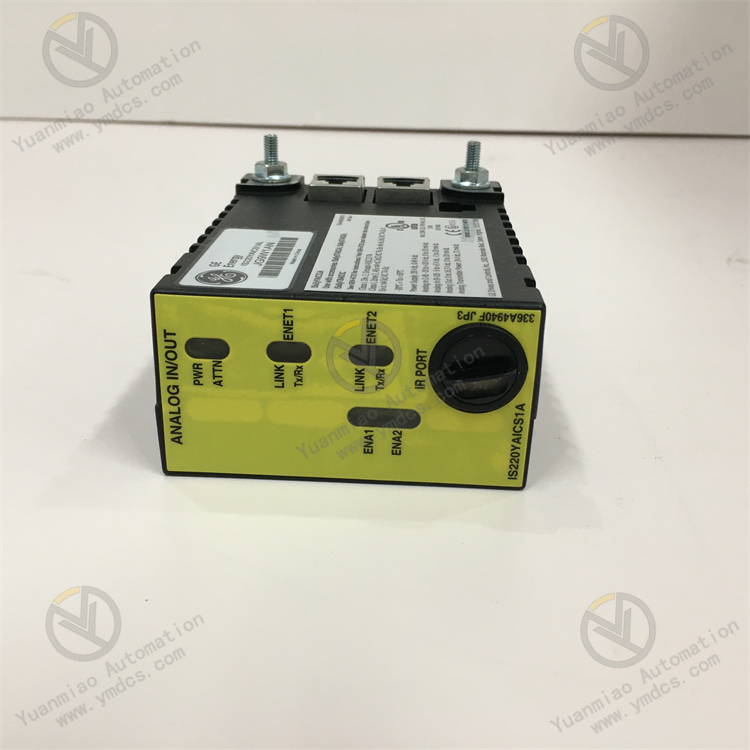
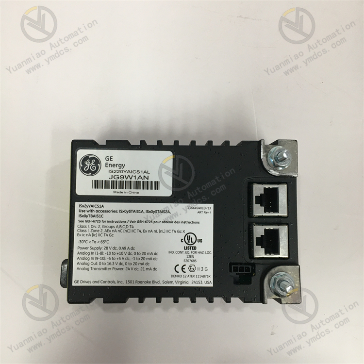
GE IS220YAICS1AL
Functional Features
- High-speed Data Acquisition and Signal Processing: Capable of state monitoring, vibration analysis, temperature monitoring, etc.
- Four Analog Input Channels: Each channel features 12-bit resolution, supports multiple input signal types (e.g., voltage, current, temperature), and can be configured for single-ended or differential input.
- Built-in Signal Conditioner: Amplifies or attenuates input signals, with onboard diagnostic functions.
- Ethernet Connectivity to Mark VIe Controller: Supports mainstream industrial protocols (Modbus TCP/IP, Profinet, Ethernet/IP, etc.) for remote data transmission and real-time monitoring. Seamlessly integrates with other I/O modules, controllers, and HMIs.
- SIL3 Compliance: Suitable for critical process safety applications, operating in harsh industrial environments (high temperature, high humidity, high vibration).
Application Areas
- Primary Applications: Gas turbines, steam turbines, and other industrial process control applications; condition monitoring and protection for rotating equipment such as compressors.
- Extended Applications: Factory automation, process control, building automation, and commercial/residential applications (e.g., security systems, HVAC).
Technical Parameters
- Analog Input Channels: 4 channels
- Input Range: Voltage 0-10V, current 4-20mA
- Input Resolution: 16 bits
- Accuracy: ±0.1%
- Communication Protocols: Supports Modbus TCP/IP, Profinet, Ethernet/IP, etc. Redundant communication available. Complies with SIL3 (Safety Integrity Level 3) for critical process safety applications.
- Operating Environment: Suitable for harsh industrial environments (high temperature, high humidity, high vibration). Low-power design ensures long-term stable operation.
Additional Features: Advanced signal analysis capabilities for high-speed data acquisition and processing, applied to condition monitoring and protection of rotating equipment (gas turbines, steam turbines, compressors, etc.).
Working Principle of GE IS220YAICS1AL Module
1. I/O Module (Input/Output Module)
- Function: Connects field devices (sensors, actuators) to the control system for signal acquisition, processing, and output.
- Input Module:
- Receives signals (voltage, current, switch signals) from field devices, converting them into digital signals via signal conditioning circuits (filtering, amplification, isolation).
- Stores data in module registers for reading by the controller (e.g., CPU) after analog-to-digital conversion (A/D conversion).
- Output Module:
- Receives digital signals from the controller, converting them into power signals (e.g., 24V DC, relay contact signals) via digital-to-analog conversion (D/A conversion) or direct drive circuits.
- Ensures system safety through isolation circuits (e.g., optoelectronic isolation) to avoid external interference.
2. Communication Module
- Function: Enables communication between the control system and external devices, other systems, or host computers, supporting industrial protocols (Modbus, EtherNet/IP, Profibus, etc.).
- Working Principle:
- Parses and encapsulates communication protocol data to ensure reliable data transmission between devices.
- Example: Ethernet modules exchange data with host computers via TCP/IP, while fieldbus modules (e.g., Profibus) communicate with distributed I/O devices via proprietary protocols.
- Typically includes protocol processing chips, communication interface circuits (RJ45, RS-485), and data buffer memory.
3. Control Module (e.g., PID Control Module)
- Function: Implements closed-loop control algorithms (e.g., PID control) to regulate industrial process parameters (temperature, pressure, flow).
- Working Principle:
- Collects real-time feedback signals (input values) from sensors, compares them with setpoints (given values) to generate deviations.
- Calculates output values via PID algorithms to drive actuators (valves, motors) and stabilize process parameters.
- Some modules support parameter self-tuning, alarm threshold setting, and fault diagnosis.
4. Analog Input Module
- Signal Acquisition: Receives analog signals from sensors (e.g., 4-20mA current, 0-10V voltage).
- Signal Processing: Filters noise and amplifies signals to appropriate levels via front-end conditioning circuits.
- Analog-to-Digital Conversion: Converts analog signals to digital quantities (e.g., 16-bit binary data) using high-precision A/D converters.
- Data Transmission: Transmits digital signals to the controller module via internal buses (e.g., PCIe or proprietary buses).
- Fault Detection: Built-in diagnostic circuits monitor signal overrun, disconnection, and other anomalies, reporting faults to the system.
Common Faults and Solutions
1. Power Supply Faults
- Symptoms: No power supply, indicator lights off; power indicator flashing or alarming; power module overheating or emitting odors.
- Causes: Faulty power supply lines (open circuit, short circuit); damaged power adapters/modules; internal power circuit short circuits or component aging.
- Solutions:
- Check input voltage/current against device specifications; replace power cables or sockets.
- Measure power output with a multimeter; replace the module if abnormal.
- Inspect internal power circuits for damaged components (e.g., bulging capacitors, burnt resistors) and replace them (professional operation required).
2. Communication Faults
- Symptoms: No communication with the host computer (PLC, computer); data errors, packet loss, or transmission interruptions; abnormal communication indicator lights (RX/TX).
- Causes: Poor communication cable connections, damage, or mismatched types (e.g., RS-485/RS-232); incorrect communication parameters (baud rate, parity, data bits, stop bits); faulty communication interface chips or driver issues.
- Solutions:
- Replug or replace communication cables; use shielded cables to reduce EMI.
- Ensure device and host computer communication parameters match; reconfigure per the manual.
- Update device drivers or firmware; return for repair or replace the module if interface chips are damaged.
3. Signal Acquisition/Output Faults
- Symptoms: Sensors fail to detect signals (no input module display); actuators unresponsive (no output voltage/current); unstable analog signals or abnormal values (e.g., temperature/pressure fluctuations).
- Causes: Faulty sensors/actuators (damage, loose wiring); malfunctioning signal conditioning circuits (e.g., amplifiers, filters); EMI causing signal distortion (cables near power lines).
- Solutions:
- Test sensor power and output signals with a multimeter; replace faulty sensors.
- Check output module loads and test output voltage/current; replace faulty components.
- Shield and ground signal cables or reroute them away from interference sources.
4. Hardware Damage or Aging
- Symptoms: Frequent crashes, restarts, or functional abnormalities; poor board slot contact causing system errors; oxidized component pins, loose solder joints, or corroded circuit boards.
- Causes: Aging electronic components (capacitors, resistors, chips); environmental factors (dust, humidity, high temperature); mechanical vibration causing loose connections or board fractures.
- Solutions:
- Clean internal dust; replace aging components (e.g., bulging capacitors).
- Replug boards or clean gold fingers with an eraser to ensure good contact.
- Improve the operating environment (add cooling fans, dust covers); repair or replace corroded circuit boards.
5. Software or Configuration Faults
- Symptoms: Abnormal device functions (e.g., ineffective parameter settings, logic control errors); program errors, loading failures, or version incompatibilities.
- Causes: Lost or incorrectly modified configuration files; outdated software or hardware-software incompatibility; logic errors in user-defined programs.
- Solutions:
- Restore factory settings or re-import correct configuration files.
- Upgrade device firmware or install compatible software versions.
- Debug or reset user programs per the manual to correct logic errors.