Description
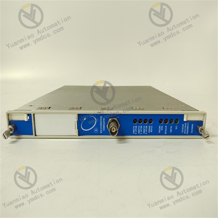
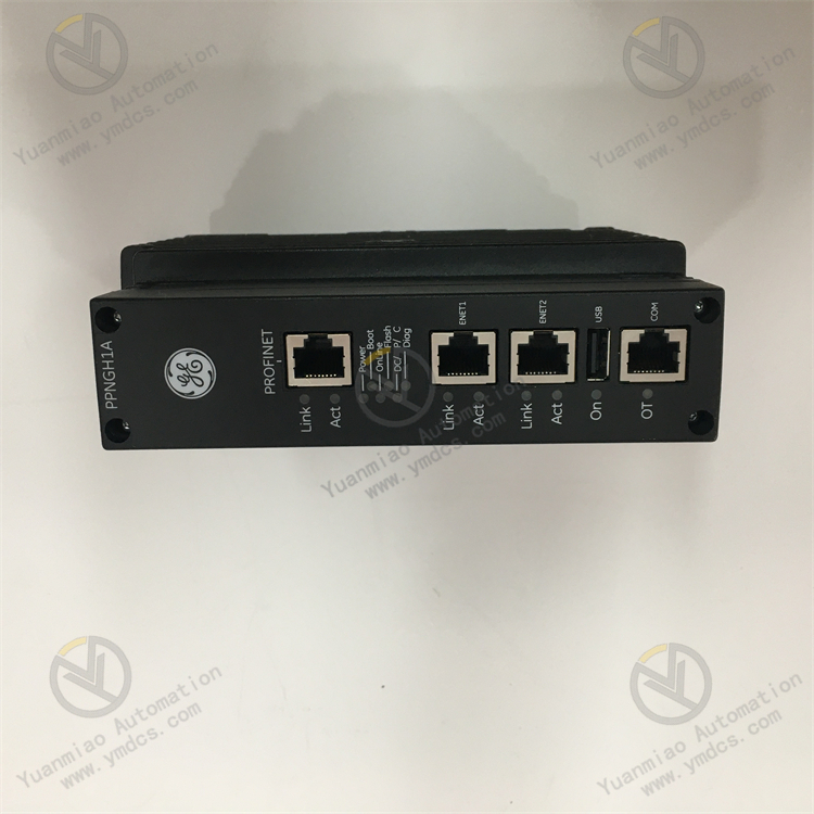
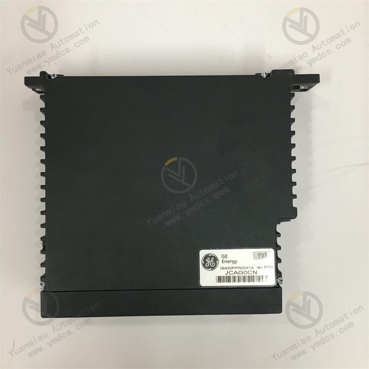
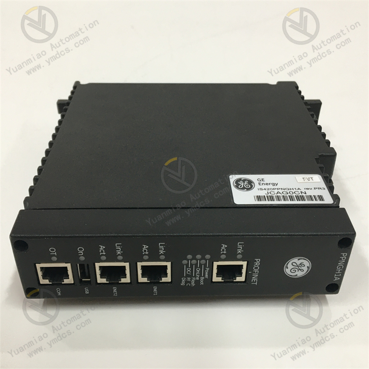
GE IS420PPNGH1A
Functional Features
- Powerful Communication Function: As a Profinet gateway, it can connect the Mark VIe controller to the Profinet local area network, enabling high-speed communication between the controller and Profinet I/O devices. It can manage the communication of all Profinet devices in the network, convert the data format between the Profinet network and the Mark VIe system, and also guide data packets within the Profinet network to ensure efficient data arrival at the destination.
- Dedicated to Turbine Protection: It is an emergency turbine protection board in the GE Mark VIeS safety control system, monitoring key parameters such as the speed and vibration of the turbine. It has the ETS function to prevent the equipment from overspeeding or getting out of control and can respond quickly in case of abnormal situations.
- High Reliability: It complies with the SIL3 standard, supports dual-channel or triple redundancy configuration, has strong anti-interference ability, is suitable for harsh environments such as high temperature, high humidity, and high vibration, and adopts advanced diagnostic functions to detect problems such as sensor failures and data anomalies.
Technical Parameters
- Processor: It uses a 1066MHz Intel EP80579 processor.
- Memory: It is equipped with 256MB DDR2 SDRAM.
- Operating System: It runs the QNX Neutrino operating system.
- Communication Ports: It has 1 RJ-45 shielded twisted pair 10/100Mbps port for connecting Profinet I/O devices and 2 RJ-45 shielded twisted pair 10/100Mbps ports (ENET1, ENET2) for Ionet communication with the Mark VIe controller.
- Data Rate: The maximum supported Profinet data rate is 6kb/ms.
- Dimensions and Weight: The dimensions are approximately 283mm×320mm×190mm, and the weight is approximately 2.3kg or 2.4 pounds.
- Operating Temperature: 22°F to 149°F (-5.56°C to 65°C).
Application Areas
- Energy Field: It is used in control systems such as gas turbines, steam turbines, and wind power generation to achieve precise control and protection of power generation equipment and ensure the stable and safe power production.
- Oil and Gas Industry: It is suitable for scenarios such as pipeline monitoring, compressor control, and drilling platform automation, helping to improve production efficiency and safety and reduce manual intervention.
- Manufacturing Industry: It can be used for high-precision motion control and production line automation, such as in the automotive manufacturing and machining industries, to achieve automated and intelligent production processes and improve product quality and production efficiency.
Working Principle of GE IS420PPNGH1A
- Overview of GE Mark VIe Turbine Control System
Mark VIe is a distributed control system (DCS) designed by GE for rotating machinery such as steam turbines and gas turbines, used to achieve the full process control of turbine startup, operation, regulation, protection, and shutdown. The system consists of multiple modular components, including:
- Processor Module: Executes control logic and algorithms.
- I/O Module: Collects sensor signals (such as temperature, pressure, and speed) and outputs control signals.
- Communication Module: Enables data interaction within the system and with external devices.
- Power Supply Module (such as IS420PPNGH1A): Provides reliable power supply for each module.
- Core Functions of IS420PPNGH1A Power Supply Module
As the "energy hub" of the system, the main functions of this module include:
- Input Power Conversion
Converts the externally input alternating current (AC) power (usually 100 - 240VAC) into the direct current (DC) power required by the system (such as +5V, +12V, -12V, etc.) to supply power to other modules. - Power Stabilization and Filtering
Eliminates fluctuations, noise, and interference of the input power through a voltage regulator circuit and filtering elements (such as capacitors and inductors) to ensure the stability and purity of the output power and avoid control system failures caused by abnormal voltages. - Redundancy and Fault Tolerance Design
In large industrial systems, the power supply module usually supports redundant configuration (such as parallel connection of dual power supply modules). When a single module fails, the redundant module automatically takes over the power supply to ensure the uninterrupted operation of the system. - Status Monitoring and Protection
The built-in monitoring circuit real-time monitors parameters such as output voltage, current, and temperature. When abnormalities such as overvoltage, overcurrent, and overheating occur, it automatically triggers protection mechanisms (such as closing the output and alarming) to prevent damage to the module and the system.
- Working Principle
- Input Stage: Power Access and Preliminary Processing
- Converts the AC power into pulsating DC through a rectifier bridge.
- Filters through a large-capacity electrolytic capacitor to smooth the voltage waveform and obtain a relatively stable DC voltage (such as about 300VDC).
- Input Power: The module accesses the external AC power (such as 220VAC) and suppresses external electromagnetic interference through an EMI filter (electromagnetic interference filter), while preventing the interference generated by the module itself from being fed back to the power grid.
- Rectification and Filtering:
- Power Conversion Stage: AC-DC Conversion to the DC Voltage Required by the System
- Switching Power Supply Technology:
The module adopts switching mode power supply (SMPS) technology. Through high-frequency switching devices (such as MOSFETs and IGBTs), the rectified DC voltage is converted into a high-frequency pulse signal, and then through a transformer step-down (or step-up) and secondary rectification and filtering, multiple low-voltage DC voltages required by the system (such as +5V, ±12V, etc.) are obtained. - Advantages: Compared with traditional linear power supplies, switching power supplies have higher efficiency (up to 80%-90%), smaller size, and less heat generation, and are suitable for long-term stable operation in industrial scenarios.
- Voltage Regulation and Feedback Control
- Voltage Regulation:
Monitors the output voltage in real-time through a feedback loop. When the output voltage deviates from the set value due to load changes or input voltage fluctuations, the pulse width modulation (PWM) controller automatically adjusts the conduction time (duty cycle) of the switching device to maintain the stability of the output voltage. - Multiple Outputs:
The module usually provides multiple independent DC outputs to supply power to the processor, I/O module, communication module, etc. respectively, avoiding power interference between each module. - Protection and Monitoring Functions
- Overvoltage Protection (OVP): When the output voltage exceeds the set threshold, quickly cut off the power supply or trigger a clamping circuit to prevent high voltage from damaging downstream modules.
- Overcurrent Protection (OCP): When an abnormal increase in output current (such as load short circuit) is detected, immediately turn off the switching device to avoid overheating or burning of the module.
- Overheat Protection (OTP): Monitors the internal temperature of the module through a temperature sensor. When the temperature exceeds the safe range, automatically reduce the output power or stop working until the temperature returns to normal.
- Status Indication: Displays the working status of the module in real-time through LED indicators (such as power normal and fault alarm), facilitating maintenance personnel to quickly troubleshoot problems.
- Redundancy Configuration (if applicable)
In scenarios with high reliability requirements, multiple IS420PPNGH1A modules can form a redundant power supply system: - Parallel Redundancy: Multiple modules supply power simultaneously and evenly divide the load current; when a certain module fails, the other modules automatically assume the entire load.
- Primary-Backup Redundancy: One module is mainly used for power supply, and the rest of the modules are in hot standby; when the main module fails, the standby module seamlessly takes over the power supply through a switching circuit.
- Application Scenarios and Key Characteristics
- Typical Applications
- Gas Turbine/Steam Turbine Control: Provides power for the core control modules of the Mark VIe system to ensure the stable operation of the turbine in scenarios such as power generation, chemical industry, and petroleum.
- Industrial Automation System: As a highly reliable power supply module, it is suitable for industrial environments with extremely high requirements for power supply stability (such as continuous production lines and large unit control).
- Key Characteristics
- Wide Input Voltage Range: Supports 100-240VAC input to adapt to the power grid voltages in different regions.
- High Reliability: Adopts industrial-grade components and has undergone harsh environmental tests (such as vibration, shock, and high and low temperatures), making it suitable for harsh working conditions.
- Hot Swap Design: Supports online replacement of modules to avoid system downtime and improve maintenance efficiency.
- Compliance with Industry Standards: Follows industrial standards such as IEEE and ISO to ensure compatibility and safety with other devices.
Common Faults and Solutions
- Common Fault Types and Causes
- Abnormal Power Output (No Voltage/Voltage Instability)
- Input power failure (such as voltage exceeding the rated range of the module, input cable loose or broken).
- Internal fuse of the module blown (caused by overcurrent, short circuit, or power surge).
- Aging of the power supply module, damage to internal components such as capacitors and resistors.
- Causes:
- Impact: Causes the control system to lose power or voltage fluctuations, which may lead to shutdown, data loss, or equipment damage.
- Overheating Alarm
- Poor ventilation in the module installation environment, blocked heat dissipation (such as dust accumulation, fan failure).
- Long-term full-load operation or internal component failure (such as poor contact of the heat sink, fan stop).
- Causes:
- Impact: Triggers the overheat protection mechanism, and the module automatically powers off, affecting the stability of the system.
- Abnormal Indicator Lights (such as power light not on or flashing)
- The module is not properly powered on (input power not connected or terminal loose).
- Internal hardware failure (such as control circuit damage, logic chip abnormal).
- Abnormal communication with other modules (possibly due to power fluctuations causing data transmission interruption).
- Causes:
- Impact: Unable to judge the status of the module through the indicator lights, increasing the difficulty of maintenance.
- Frequent Restart or Freeze of the Module
- Harmonic interference or excessive voltage ripple in the input power.
- Module firmware failure (such as program error, version incompatibility).
- Poor contact of internal connectors or virtual soldering of circuit board solder joints.
- Causes:
- Impact: Causes the control system to be unstable and may trigger chain failures.
- Communication Failure (disconnected from the main control module or other devices)
- Insufficient power supply of the power supply module, resulting in the communication interface circuit unable to work properly.
- Communication cable damaged or interface pins oxidized, bent.
- Incorrect module address setting or conflict with other devices.
- Causes:
- Impact: The system cannot obtain the power status data, which may lead to monitoring failure.
- Fault Troubleshooting and Solutions
- Troubleshooting of Abnormal Power Output
- Step 1: Check the input power
Use a multimeter to measure the input voltage and confirm whether it is within the rated range of the module (such as AC 100-240V or DC 24V, subject to the manual).
Check whether the input cable, circuit breaker, and terminal block are loose or damaged, and re-tighten or replace the faulty components. - Step 2: Check the internal fuse
After powering off, open the module housing (follow electrical safety specifications) and check whether the fuse is blown.
If it is blown, replace the fuse with the same specification (note: do not use copper wire or other conductors instead), and check whether there is a short circuit hidden danger (such as downstream load failure). - Step 3: Replace the module for testing
If the fuse blows frequently or there is no output, it may be that the internal components of the module are damaged, and a spare module needs to be replaced. - Solution to Overheating Problem
- Step 1: Clean the heat dissipation channel
After powering off, use compressed air to blow off the dust on the surface of the module and the ventilation port to ensure that the heat dissipation holes are not blocked. - Step 2: Check the fan status
After powering on, observe whether the fan rotates. If it stops rotating or the speed is abnormal, replace the fan assembly (the fan of some modules can be replaced separately). - Step 3: Optimize the installation environment
Ensure that the module is installed in a well-ventilated control cabinet and avoid close parallel installation with heating elements (such as frequency converters and high-power resistors).
If necessary, add a cooling fan or air conditioner in the cabinet to control the ambient temperature within the rated range of the module (usually 0-50°C). - Handling of Abnormal Indicator Lights
- Step 1: Confirm the power supply status
Check whether the input power indicator light (such as the PWR light) is on. If it is not on, repeat the "Troubleshooting of Abnormal Power Output" steps. - Step 2: Check the module installation and connection
Ensure that the module is correctly inserted into the backplane or rail, and the connector is not loose or skewed. Re-plug the module to remove the oxide layer. - Step 3: Firmware upgrade or return to the factory for repair
If the indicator light flashes and is accompanied by an error code (such as read through the serial port or host computer), it may be a firmware failure. Try to upgrade to the latest version.
If the hardware is damaged (such as the indicator light is not on and there is no output), contact GE after-sales or an authorized maintenance provider to return the factory for inspection. - Handling of Frequent Restart or Freeze
- Step 1: Suppress power interference
Install a power filter or voltage regulator on the input side to reduce the impact of harmonics and surges.
Ensure that the cable of the power supply module is separated from that of high-power electrical equipment (such as motors and contactors) to avoid electromagnetic interference. - Step 2: Check the firmware compatibility
Confirm that the module firmware version is compatible with the main control system. You can refer to the GE official technical document or contact technical support to obtain the adapted version. - Step 3: Troubleshoot hardware contact problems
Visually check whether the solder joints on the circuit board are False welding or cracked, and use a multimeter to detect whether the voltage at the key test points is stable.
If the components are damaged (such as capacitor bulging, resistor ablation), professional personnel are required to replace the components or replace the module as a whole. - Troubleshooting of Communication Failure
- Step 1: Check the communication connection
Visually check whether the communication cable (such as RS-485, Ethernet) is damaged, and whether the interface pins are bent or oxidized. Re-plug the cable or replace the spare parts. - Step 2: Confirm the communication parameters
Check whether the address, baud rate, protocol, and other parameters are consistent with the system through the module configuration tool (such as GE's Proficy software) to avoid conflicts. - Step 3: Test independent communication
Connect the module Alone to the debugging device (such as a laptop) to test whether data can be normally transmitted and received to Exclude the interference of other devices.
- Maintenance Suggestions
- Regular Inspection:
Check the status of the module indicator lights, the sound of the fan operation, the input voltage, and the temperature every quarter, and record the operation data.
Clean the internal dust of the module once a year and check the tightness of the connectors. - Spare Parts Management:
When storing the spare module, pay attention to moisture prevention and anti-static (use anti-static packaging bags), and regularly power on for testing (to avoid capacitor aging caused by long-term storage).