Description
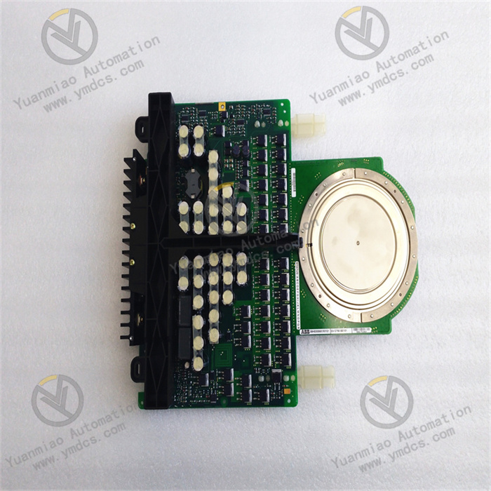
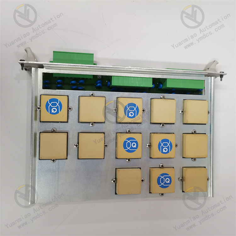
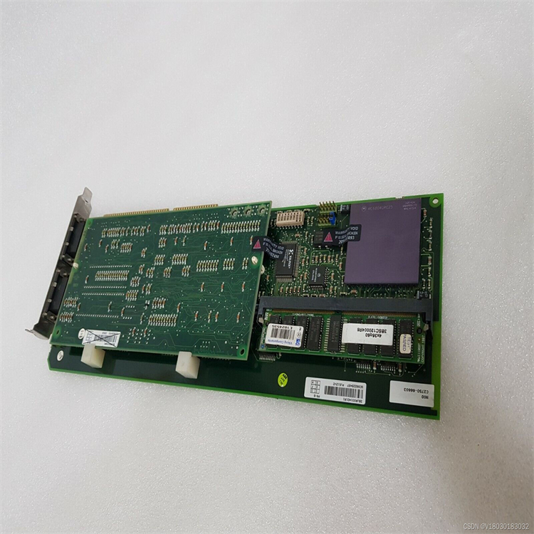
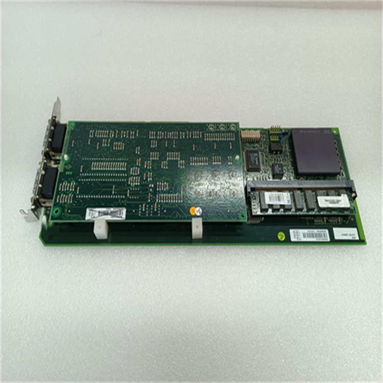
ABB PU512V2 3BUR001401R1
I. Overview
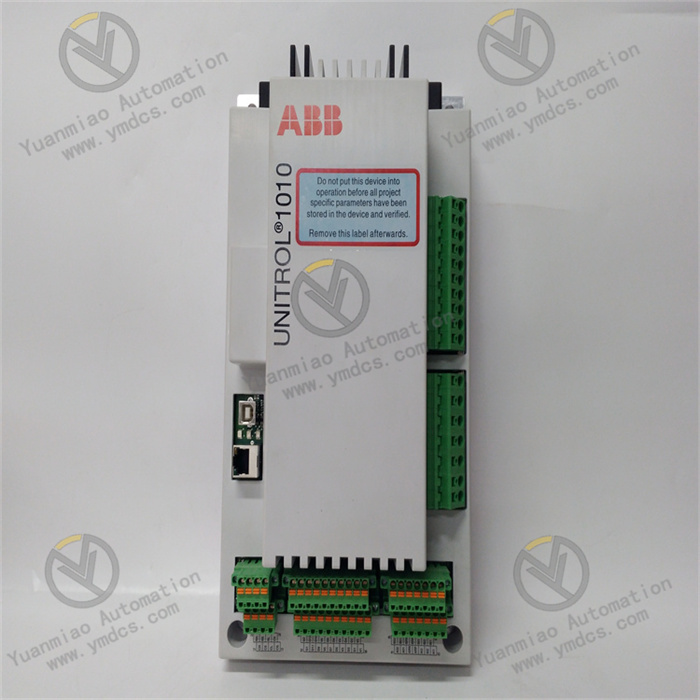
The PU512V2 3BUR001401R1 is a programmable controller module introduced by ABB, serving as the central processing unit (CPU) module of the AC500 series PLC. As the core of industrial automation control systems, this module features high-speed data processing, complex logic operation, and multi-task management capabilities. It supports multiple communication protocols and expansion modules, making it suitable for small to medium-sized automation systems in industries such as power, metallurgy, chemical, and manufacturing. Its design balances performance and reliability to meet the needs of process control, machine automation, and distributed systems.
II. Functional Features
High-Performance Computing Capability
- Equipped with a 32-bit microprocessor running at up to 400MHz, supporting 20 million logical operations (Boolean instructions) per second to meet high-speed control requirements.
- Built-in 512KB program memory and 1MB data memory, supporting large program storage and complex data processing.
Multi-Protocol Communication Interfaces
- Integrates 2×Ethernet (10/100Mbps) and 2×RS485/RS232 communication interfaces, supporting protocols such as Modbus, EtherNet/IP, and PROFINET.
- Enables seamless communication with HMI, SCADA systems, and third-party devices for data interaction and remote monitoring.
Flexible Expansion and Configuration
- Supports hot-swappable expansion modules (e.g., I/O modules, communication modules), with a maximum of 64 expansion units to adapt to complex system requirements.
- Enables visual programming via ABB Control Builder software (supporting programming languages such as LD, FBD, and ST), simplifying engineering configuration.
High-Reliability Design
- Operating temperature range: -25°C to +70°C, adapting to harsh industrial environments; resistant to vibration (10-500Hz, 5g) and shock (30g, 11ms).
- Supports redundant power input (24V DC) and battery backup (data retention) to ensure programs and data are not lost during power outages.
III. Technical Parameters
| Parameter Category | Specific Indicators |
|---|---|
| Power Supply Voltage | 24V DC (±10%), power consumption ≤10W |
| Processor | 32-bit RISC processor, 400MHz clock speed |
| Memory Configuration | Program memory: 512KB, data memory: 1MB, supports SD card expansion (up to 32GB) |
| Communication Interfaces | - 2×RJ45 Ethernet (10/100Mbps) - 2×RS485/RS232 (configurable for Modbus RTU) - 1×USB 2.0 (for program download) |
| I/O Expansion Capability | Maximum support for 4096 digital I/O points or 512 analog I/O points, compatible with S800 I/O modules |
| Programming Languages | Complies with IEC 61131-3 standards: LD, FBD, ST, SCL, IL |
| Physical Dimensions | 170mm × 40mm × 110mm, weight approx. 0.4kg |
| Protection Level | IP20 (suitable for installation in control cabinets) |
| Certification Standards | CE, UL, ISO 9001, compliant with EN 61000 electromagnetic compatibility standards |
IV. Working Principle
As the core module of the PLC, the PU512V2 follows a cyclic scanning mechanism in its workflow, divided into the following stages:
Input Sampling Stage
- Acquires input signals from field devices (e.g., sensors, buttons) through extended I/O modules and stores them in the input image register.
Program Execution Stage
- Executes user programs in scanning order, performs logical operations based on data from the input image register and internal registers, and stores results in the output image register.
Output Refresh Stage
- Outputs the status of the output image register to actuators (e.g., motors, valves) via I/O modules to achieve device control.
Communication and Diagnosis Stage
- Processes requests from communication interfaces (e.g., receiving HMI commands, sending data to SCADA);
- Self-diagnoses internal hardware status (e.g., memory errors, communication anomalies) and alarms via LED indicators.
V. Common Faults and Solutions
| Fault Phenomenon | Possible Causes | Solutions |
|---|---|---|
| Power light (PWR) not on | Loose power connection or abnormal voltage | Check power cable connections, measure input voltage within 24V DC (±10%), and replace the power module. |
| RUN light not on | Program errors (e.g., syntax errors, infinite loops) | Check program logic via Control Builder software, download error-free programs, and restart the module to clear the cache. |
| Communication interruption | Network cable failure, IP conflict, or protocol configuration error | Detect network cable continuity, replace RJ45 connectors, and verify IP addresses and communication protocol parameters (e.g., baud rate, parity bit). |
| I/O module unresponsive | Poor expansion bus contact or module address conflict | Re-plug I/O modules, check bus connectors, and ensure module addresses are within the allowable range (e.g., 0-63). |
| Program loss or abnormality | Insufficient battery power (data backup failure) | Replace the internal battery (3.6V lithium battery), re-download the program, and verify the data retention function. |
| Module overheating | Poor control cabinet heat dissipation or high ambient temperature | Add cooling fans to ensure good ventilation around the module; install a temperature-controlled cooling device if the ambient temperature exceeds 70°C. |
VI. Extended Application Scenarios
The PU512V2 is often used with ABB S800 I/O modules, TP500 touch screens, and third-party devices. Typical applications include:
- Power Industry: Substation relay protection systems, generator set sequence control;
- Manufacturing Industry: CNC machine logic control, automation production line cycle control;
- Chemical Industry: Reactor temperature/pressure closed-loop control, filling equipment process automation;
- Water Treatment: Sewage treatment plant pump/valve interlocking control, water quality monitoring systems.


