Description
GE IS200DSFCG1AEB
I. Basic Information
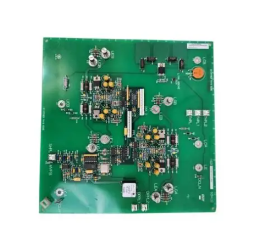
Model: IS200DSFCG1AEBBrand: GEProduct Line: Driver Shunt Feedback Board for GE Speedtronic Mark VI turbine drive control system. It realizes high-precision current sampling of IGBT drive branch and DC bus, adopts optoelectrical isolation and MOV surge protection, provides closed-loop feedback signal for frequency conversion main control, with on-board jumper configuration and LED fault diagnosis function, widely used in high-power frequency conversion power units of thermal power, petrochemical and metallurgical industries for current closed-loop regulation and power loop safety protection。
Product Positioning
IS200DSFCG1AEB is the core signal acquisition hardware of high-power power conversion system. It converts high current on the power side into standard weak current feedback signals through shunt sampling and optoelectrical isolation, realizes precise torque and speed closed-loop control of frequency converter. It integrates multi-level hardware fault detection and surge protection functions, can quickly lock faults and trigger IGBT pulse blocking to avoid power device burnout. It supports two power range configurations of 1000A and 1800A, with strong spare part versatility, and is the preferred replacement accessory for the renovation and fault maintenance of legacy Mark VI frequency conversion power cabinets.
Hardware Architecture
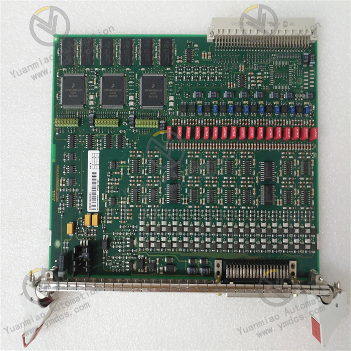
Flame-retardant FR4 PCB with basic insulating protective coating, consisting of five core functional units: precision shunt current sampling unit, optoelectrical isolated signal conversion unit, MOV transient surge protection unit, jumper configuration & fault diagnosis unit, standard backplane connector docking unit. Each board corresponds to one phase power loop, and the three-phase system needs three boards to form a complete closed-loop control sampling system.
Mounting Specification
Standard vertical slot limit installation in power cabinet, compliant with IEC vibration, humidity cycling and power aging reliability standards. Different suffix revised versions of the same series can be compatibly replaced without modifying primary power wiring and main control feedback loops.Dimension: 50.8mm×76.2mm, net weight: 0.49kg, total packaging weight: 1.2kg.
Compatible Systems
- Hardware: Mark VI frequency conversion power unit, IGBT drive power bridge, DC bus fuse, three-phase frequency conversion main control unit, shielded sampling cables, 24VDC control power supply;
- Test Tools: Multimeter, oscilloscope, GEI-100263 official manual, ToolboxST diagnostic software;
- Upper Platforms: Power plant DCS, fault waveform recording server, remote drive operation and maintenance platform;
- Application Industries: Gas/steam turbine variable frequency drive system, captive power plant excitation inverter device, oil & gas compressor drive frequency conversion cabinet, metallurgical main drive power control system.
Product Characteristics
- Precision differential sampling circuit features high linearity and low temperature drift, realizing millisecond-level current closed-loop regulation and high-precision torque control for high-power frequency conversion equipment.
- Full-link optoelectrical isolation plus MOV dual surge protection effectively eliminates industrial common-mode interference and transient voltage spikes to protect main control and power devices from breakdown damage.
- Three groups of configurable jumpers support fast switching of two current ranges, adapting to power units of different capacities and reducing spare part inventory types.
- Five-channel LED status indicators realize on-site visual fault location, greatly shortening the troubleshooting cycle of high-power power cabinets.
- Self-locking anti-loose connectors adapt to strong vibration working conditions, avoiding intermittent loss of sampling signals caused by terminal virtual connection.
- Pin-compatible plug-and-play replacement realizes rapid renovation of legacy control cabinets and shortens unit outage maintenance time.
II. Technical Specifications
2.1 Electrical Parameters
- Control Power Supply: DC 22~28V, typical power consumption 8W
- Selectable Current Range: 1000A / 1800A via jumper setting
- Sampling Accuracy: Linear error ≤±0.2%FS, temperature drift ≤50ppm/℃
- Dielectric Withstand Voltage: 2000VAC 1min between power side and control side, ±4kV ESD, ±2kV EFT protection, built-in MOV surge protection device.
2.2 Signal & Interface Parameters
- Sampling Channel: Four-way differential sampling for upper/lower IGBT bridge and DC bus current
- Isolation Specification: High-speed optocoupler full galvanic isolation, bandwidth ≥1MHz
- Configuration Interface: Three pairs of jumper pins for range and drive mode setting
- Status Indicator: 5 LEDs for drive status, DC bus normal and fault alarm
- Connector: 3 groups of Stab-On self-locking multi-pin connectors.
2.3 Environmental Specifications
- Operating Temperature: 0℃ ~ +60℃; Storage Temperature: -40℃ ~ +85℃
- Relative Humidity: 5%~95%RH, non-condensing, no corrosive gas
- Vibration Compliance: IEC 60068-2-6, CE & UL certified, MTBF≥200000h
- Protection Class: IP20 for bare board, IP30 in sealed metal control cabinet.
2.4 Mechanical Parameters
- Mounting: Vertical limit fixed installation in standard power cabinet slot
- Dimension: 50.8mm×76.2mm, net weight: 0.49kg
- PCB: V0 flame-retardant FR4 with basic insulating coating
- Interfaces: 3 self-locking connectors, 3 configuration jumpers, 5 status LEDs, MOV surge protection component.
III. Key Features
3.1 High-Precision Closed-Loop Current Sampling Feedback
Converts large current on the power side into standard isolated feedback signals, realizes high-stability torque and speed closed-loop regulation, suppresses load and grid disturbance oscillation to guarantee safe and stable operation of turbine driving equipment.
3.2 Dual Safety Protection of Galvanic Isolation & Surge Suppression
Optoelectrical isolation eliminates strong and weak current common-mode interference; MOV diverts transient voltage spikes to avoid breakdown of precision sampling and isolation devices, preventing large-area burnout accidents of power units.
3.3 Flexible Jumper Configuration for Multi-Capacity Adaptation
Supports two mainstream current range settings, one board for one phase power loop, flexible combination to meet the sampling requirements of different capacity three-phase frequency conversion systems with strong spare part compatibility.
3.4 Visual On-Site Fault Diagnosis via Multi-Channel LED Indicators
Real-time display of IGBT drive and DC bus operating status, latch fault alarm to quickly locate fault phase and fault type without upper computer software, greatly improving on-site maintenance efficiency.
3.5 Hardware Fault Latching & Instant Safety Interlock
Triggers immediate drive pulse blocking after overcurrent and drive fault detection, realizes millisecond-level protection of power units to prevent fault spread and protect high-value power devices such as IGBT and DC bus capacitors.
IV. Working Principle
After power-on self-test of sampling, isolation and diagnostic circuits, the board collects instantaneous current signals of IGBT branches and DC bus through precision shunt resistors. The signals are filtered, amplified and optoelectronically isolated and then uploaded to the frequency conversion main control unit for closed-loop PID operation. The built-in MOV device suppresses transient surge voltage in real time. Once overcurrent or drive abnormality is detected, the hardware latches the fault state, lights the fault LED and sends an interlock signal to the main control to block the IGBT drive pulse for safe shutdown. The preset jumper ensures accurate current sampling matching the rated capacity of the power unit.
V. Application Scenarios
- Thermal & combined cycle power plant Mark VI turbine frequency conversion drive system: Closed-loop current sampling, IGBT fault monitoring and power unit overcurrent safety interlock protection.
- Captive power plant excitation inverter equipment: Excitation power bridge feedback collection, DC bus status monitoring and power fault safety protection.
- Oil & gas pipeline compressor station drive frequency conversion cabinet: High-precision torque closed-loop control and on-site fault diagnosis operation and maintenance.
- Metallurgical rolling mill main drive frequency conversion system: Three-phase power loop current acquisition, load disturbance suppression and power device anti-surge protection.
- Legacy GE Mark VI power cabinet renovation: Direct replacement of aging feedback boards with original wiring and slot compatibility to shorten unit outage maintenance duration.